Explosion-Proof Telephone System: SIP and Paging Integration
Learn how to network explosion-proof telephones through direct SIP registration, FXS gateways and hybrid architectures, with paging integration, resilience and commissioning guidance.
Becke Telcom
Installing an explosion-proof telephone at a hazardous site solves only the field-terminal requirement. Reliable communication also depends on how the telephone reaches the control room, how calls are routed, how operators identify the calling location, and how a confirmed incident is escalated to paging or emergency notification.
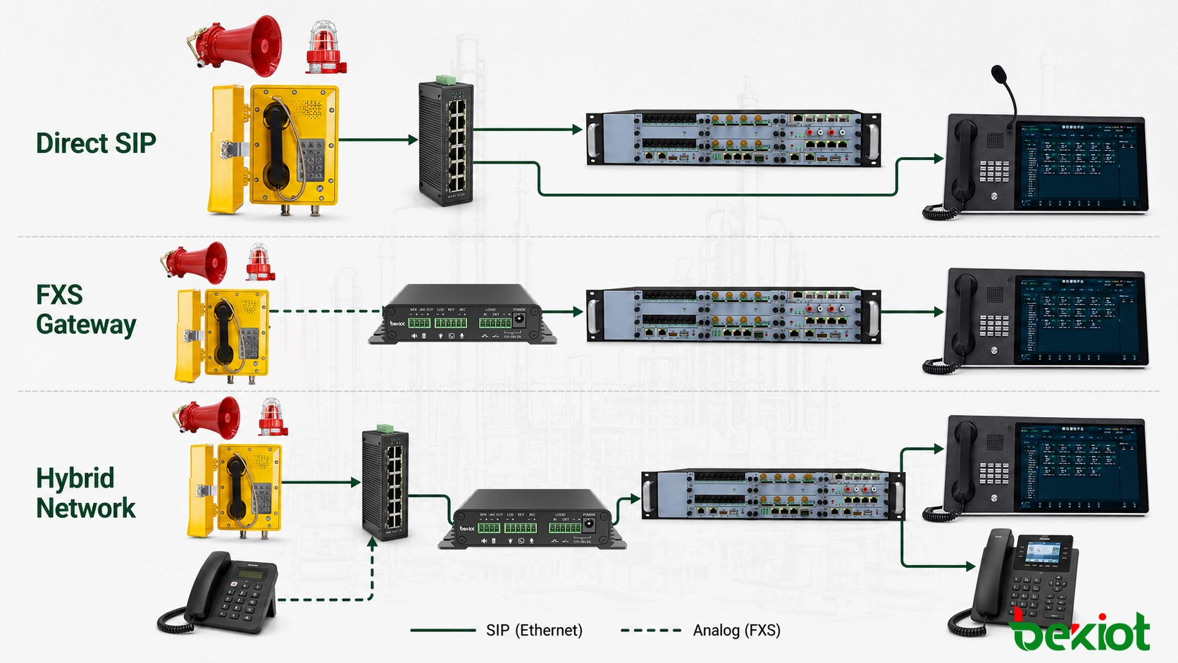
Common designs include direct SIP registration, analog telephone access through an FXS gateway, and hybrid networks that retain existing lines while introducing IP endpoints. The appropriate architecture is determined by the installed cabling, network availability, operating procedure and failure policy—not simply by the number of features listed for the telephone.
Define the Boundary Between Hazardous and Safe Areas
Network design should begin with the hazardous-area boundary. Field telephones may be installed around process units, loading areas, tank farms or other locations identified by the site risk assessment. Voice gateways, IP PBX servers, dispatch equipment and core network switches are normally placed in a control room, equipment room or another suitable safe area.
Keeping central equipment outside the classified area reduces the amount of active equipment exposed to hazardous conditions and makes maintenance more practical. Field wiring, cable entries, junction boxes, grounding and power delivery still require individual assessment according to their locations and functions.
Any switch, power unit or connection box installed inside a classified area requires its own suitability assessment. It does not inherit the protection status of the telephone simply because both devices belong to the same communication system.
Building-to-building connections require additional attention. Long copper runs may be exposed to lightning, electrical interference and differences in ground potential. Fiber can be used for backbone links where practical, while copper Ethernet or telephone wiring is limited to the final connection near the field endpoint. Cable routing must remain consistent with the site's electrical and hazardous-area installation requirements.
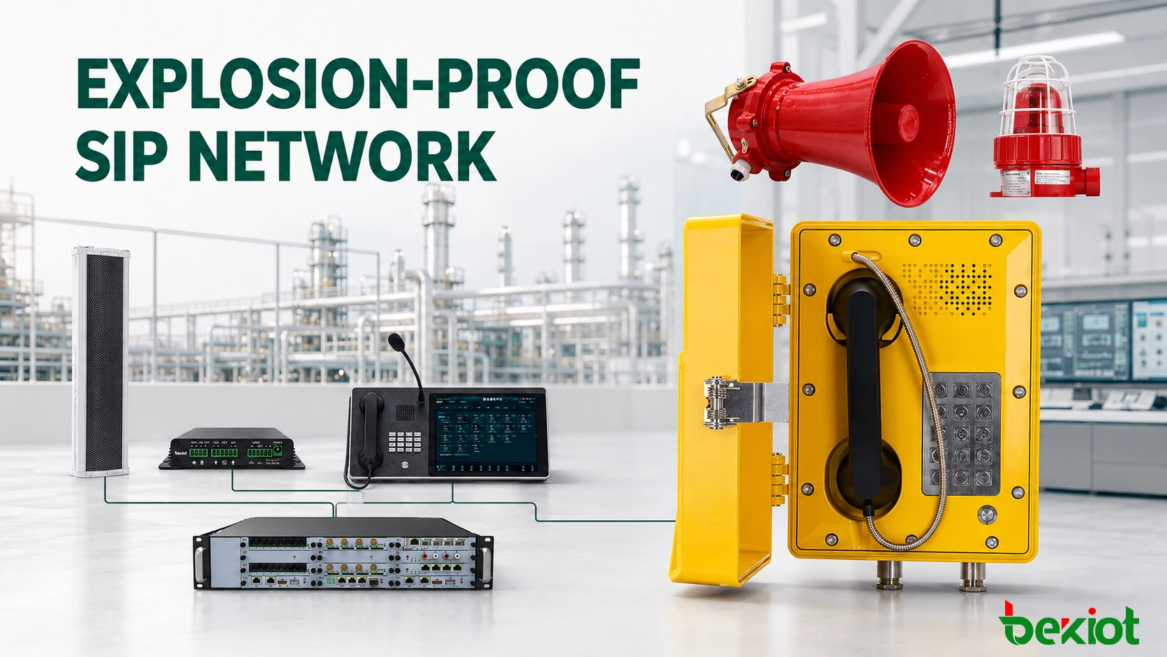
Typical system boundary: hazardous-area telephone → field cabling or industrial network → safe-area switch or voice gateway → IP PBX → dispatch console and duty-room telephone.
Choose the Appropriate Access Architecture
The telephone interface determines the required field cabling, access equipment and platform configuration. New installations can often use direct SIP access, while retrofit projects may need to preserve analog lines that remain in acceptable condition.
Direct SIP Registration
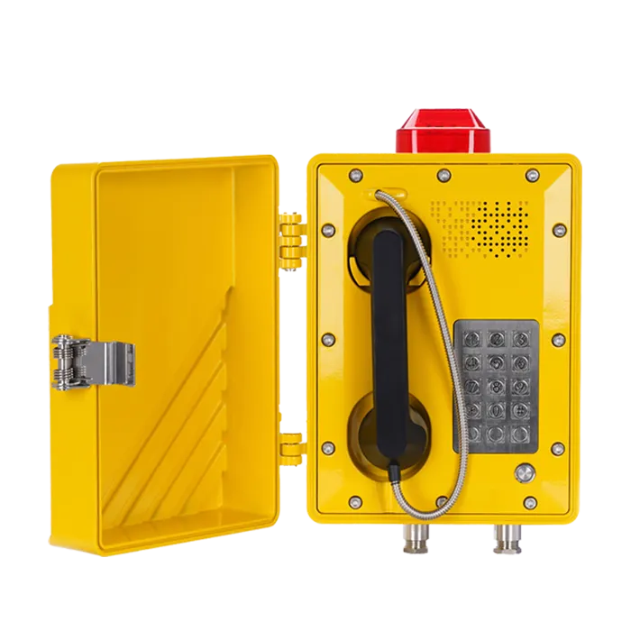
A SIP explosion-proof telephone connects to an industrial Ethernet network and registers with an IP PBX, SIP server or dispatch platform. The platform assigns an extension to the endpoint and applies the required call permissions and routing rules.
Direct SIP path: explosion-proof telephone → industrial switch → IP PBX or SIP server → dispatch console, duty-room telephone and optional recording system.
Direct SIP access works best where industrial Ethernet already reaches the required field locations. Extension configuration and call routing can be managed centrally, while additional endpoints can be introduced without installing a separate analog pair for every telephone.
A model such as the Becke Telecom EX-BH621 can be included as a SIP field endpoint in this architecture. Its suitability for a specific hazardous location, power method and system interface must still be checked against the project conditions and current product documentation.
Record the power source for every endpoint as part of the network schedule. Where network power is used, verify the switch power budget, cable length and backup-power arrangement for the complete access layer. Where a separate power source is used, document power and data routes independently so that an offline endpoint can be diagnosed without opening unrelated equipment.
Analog Telephone Access Through an FXS Gateway
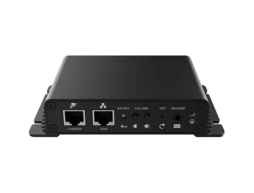
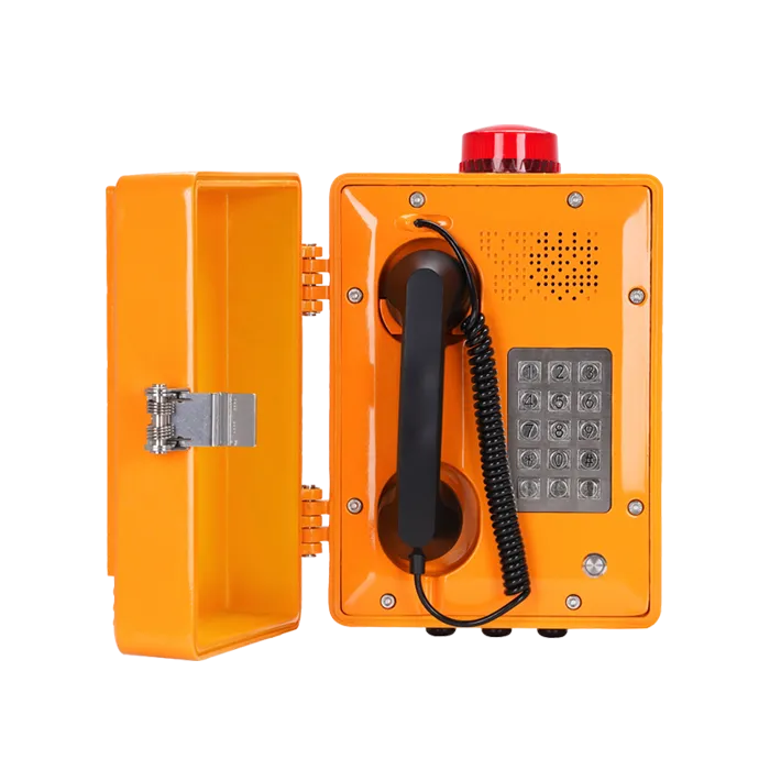
Existing analog explosion-proof telephones can be connected to the FXS ports of a voice gateway. The gateway presents those analog lines to the IP PBX as SIP extensions, allowing legacy field equipment to communicate with IP phones and dispatch consoles.
Analog access path: analog explosion-proof telephone → telephone cable → FXS voice gateway → IP PBX or dispatch platform.
Gateway access is practical when the installed analog lines and field telephones remain serviceable. Before reuse, inspect line insulation, loop length, termination quality and exposure to moisture, corrosion or electrical interference. The gateway converts the interface but cannot correct a damaged field circuit.
Assign each gateway port to a fixed field endpoint and keep that relationship unchanged unless the port map is formally updated. This avoids routing errors during maintenance or equipment replacement.
Hybrid Deployment
Large industrial sites often modernize one area at a time. Existing process units may retain analog telephones, while new buildings use SIP endpoints. Both can operate through one IP PBX when analog lines are connected through voice gateways and SIP endpoints register directly.
Hybrid deployment reduces the scope of an immediate replacement, but the migration boundary must be documented. Drawings should show which areas remain analog, which use direct SIP access and where interface conversion takes place.
Explosion-proof telephones can use direct SIP access, analog gateway conversion or a hybrid architecture.
Separate SIP Signaling from the Voice Path
SIP manages endpoint registration, call establishment, session changes and call release. The voice stream is normally carried separately by RTP. An endpoint shown as online on the IP PBX may therefore still experience silence, one-way audio or poor voice quality.
A normal call passes through four stages:
Registration: The telephone or voice gateway authenticates with the IP PBX, which records the endpoint and its current network address.
Number analysis: The platform checks the dialed number, user permissions, routing policy and destination status.
Session negotiation: The endpoints agree on compatible media parameters and establish a call relationship.
Media transport: RTP carries the voice stream along the negotiated path until the call is released.
Layer
Primary Function
Typical Fault
SIP registration
Associates the endpoint with the platform
Authentication failure or repeated registration loss
Call routing
Selects the destination and applies permissions
Rejected calls, incorrect routing or routing loops
Media negotiation
Agrees on codec and media addresses
Connected call with no audio or one-way audio
Network transport
Carries signaling and voice packets
Delay, jitter, packet loss or intermittent speech
Voice devices can be placed in a dedicated VLAN where appropriate, with access rules and quality-of-service policies applied across the actual network path. Calls should then be tested under normal production network load, particularly when traffic crosses shared uplinks or wide-area connections.
Codec planning should be consistent across telephones, gateways, servers and recording systems. Unnecessary transcoding consumes platform resources and can introduce additional delay or reduce speech quality. When analog and SIP endpoints share the same call path, verify the selected codec at the gateway as well as at the IP PBX.
Build a Numbering Plan Around Physical Locations
Extension numbers should help operators identify where a call originated. A multi-site plan can combine a site prefix, area code and endpoint number. For example, separate ranges may be assigned to the tank farm, loading area, production unit and utility building.
The dispatch interface should display both the extension and an operational location name such as “Tank Farm East” or “Loading Bay 2.” This reduces the time spent confirming the caller's position during an incident and makes gateway-port troubleshooting more efficient.
Connect Telephone Calls with the Paging Workflow
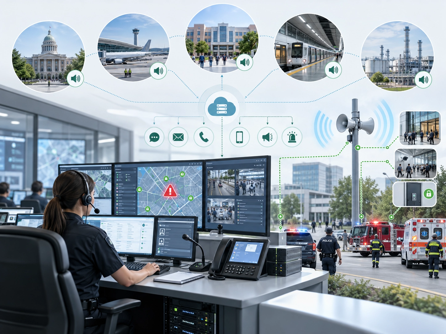
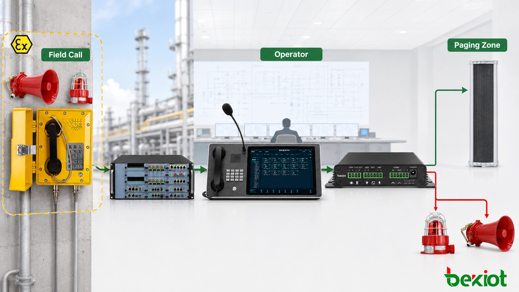
Telephone and paging systems perform different tasks. A telephone establishes a conversation between the field and an operator. A paging system distributes live or recorded audio to one or more zones. Integration normally occurs through the IP PBX, dispatch platform, paging gateway or another supported control interface.
Operator-Confirmed Paging
A field user calls the control room and reports the situation. After confirming the source, event and affected area, the operator selects the required paging zones and makes an announcement from the dispatch console.
Operator confirmation fits events that must be verified before a wider notification is issued. It also allows the message and destination zones to be adjusted according to current site conditions.
Paging Through a Dedicated Extension
Where supported, the communication platform can associate paging extensions with specific buildings, production areas or all-call groups. An authorized user calls the required extension, and the platform establishes a media path to the relevant SIP speakers, paging endpoints or PA gateway.
Define who may call each group, whether a pre-announcement tone is required, how an occupied zone is handled and how the paging session is released. Site-wide groups should be restricted to designated users rather than made available to every field extension.
Overlapping paging areas need an explicit busy policy. A second request may be rejected, queued or allowed to interrupt the active announcement according to its assigned priority. The selected result should be visible to the operator so that a rejected or delayed request is not mistaken for a completed broadcast.
Event-Triggered Recorded Messages
Alarm inputs, controllers or third-party systems may send an event to the communication platform through a supported interface. The platform can then select a destination and request playback of an assigned message.
Automatic playback relies on the complete control chain. Document the trigger source, interface, message storage location, destination zones, priority and reset condition before configuration begins.
Typical linkage sequence: field call or alarm event → source and permission check → operator confirmation or platform rule → paging-zone selection → live or recorded audio → release and status recovery.
Priority must be coordinated across the entire audio path. A high-priority call on the IP PBX does not automatically override another source at the PA amplifier. The paging gateway, PA controller and amplifier must also provide the intended priority or mute behavior.
A field call can be verified by an operator or processed by a defined platform rule before audio is sent to a paging zone.
Design for Failures, Not Only Normal Calls
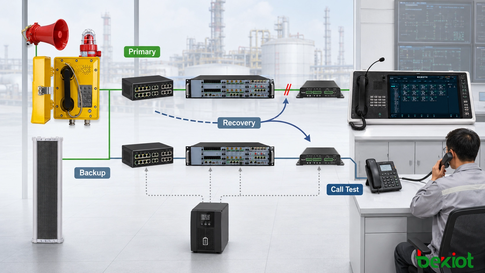
A short interruption may be inconvenient during routine operations, but the same interruption can prevent a field report from reaching the control room during an incident. Availability planning should cover power, endpoints, switches, gateways, network paths, servers and operator positions.
Failure Point
Possible Effect
Design Question
Field power
The telephone or local access equipment goes offline
Which devices require backup power, and for how long?
Industrial switch
Several SIP endpoints may disconnect together
Is there a protected power source or alternative uplink?
Voice gateway
Connected analog telephones lose access to the SIP core
How is the fault reported, and is an alternative route required?
IP PBX or SIP server
Registration and call routing may stop
Is platform redundancy or local fallback required?
Dispatch console
Centralized call handling becomes unavailable
Can a duty-room telephone receive essential calls?
PA equipment
Paging audio does not reach the selected zone
Is there a local paging source or another notification method?
Confirm the Available Protection Mechanisms
Backup registration, redundant servers, dual network paths and offline message playback require support from the relevant devices and platforms. Confirm each capability against the selected equipment and software before including it in the final system design.
Multi-site systems also need an explicit policy for wide-area network failures. If every local telephone depends on a central server, a WAN outage may interrupt calls within the same facility. Sites with higher continuity requirements may need a local call-control function or a separate fallback communication path.
Define the Expected Recovery Result
Recovery requirements should state which calls remain available, whether service returns automatically, how operators receive fault notifications and when manual intervention is acceptable. These requirements provide measurable acceptance criteria for redundancy and fallback functions.
Commission the Complete Operating Sequence
One successful test call does not demonstrate that the system is ready for operation. Commissioning should cover endpoint identification, bidirectional calling, paging-zone selection, busy handling, network interruption and service recovery.
Verify endpoint records. Confirm the extension, location name, installation point and platform identity for every telephone and gateway port.
Test calls in both directions. Place calls from the field to the dispatch console, return calls from the console and verify communication with the duty-room telephone.
Confirm location display. The operator interface should show a name that matches the physical installation point.
Evaluate speech under operating noise. Check intelligibility, listening level, one-way audio, clipping and excessive delay while nearby equipment is running.
Verify every paging destination. Test individual zones, groups and all-call functions, confirming that audio does not reach unselected areas.
Test busy and priority conditions. Confirm the expected result when a zone is already in use or a higher-priority request is received.
Interrupt network and power paths. Record which services stop, which remain available and whether endpoints recover without manual reconfiguration.
Review operational records. Compare call logs, recordings and event timestamps to verify that the systems use a consistent time source.
Save the accepted configuration as a controlled baseline. Include endpoint accounts, gateway port maps, dial plans, paging groups, network addresses and software versions. Later changes can then be compared with the commissioned state instead of relying on undocumented settings.
Acceptance testing should cover normal calls, paging integration, failure conditions and service recovery.
Commissioning is complete only when a field call can be identified, routed, answered, escalated and released under both normal and defined failure conditions. The final records should match the installed endpoint numbers, gateway ports, paging groups and recovery procedures.
FAQ
Can Existing Ethernet Cabling Be Reused for a SIP Explosion-Proof Telephone?
Existing cabling may be retained only after its category, route, condition, termination and compatibility with the required power method have been verified. A successful continuity test alone does not confirm that the cable is suitable for the complete installation.
Can DTMF Digits Be Used to Select Paging Zones?
They can be used when the IP PBX, paging platform and endpoint workflow support DTMF-based selection. Define valid digits, confirmation prompts, timeout behavior and protection against accidental all-call activation.
Can a Field Telephone Call More Than One Dispatch Center?
Multiple destinations can be implemented through sequential routing, simultaneous ringing or an operator group when supported by the IP PBX. The selected method should define how unanswered, busy and failed calls are handled.
Can SIP Paging Replace a Fire Voice Alarm System?
Not automatically. SIP telephony and paging can support operational and emergency communication, but a life-safety voice alarm application must be evaluated as a complete system under the applicable project and regulatory requirements.
Does Every Field Call Need to Be Recorded?
Recording policy should follow the site's operating rules, privacy requirements and incident-management procedures. Recording may be assigned by extension, role, call type or destination rather than applied identically to every call.