Induced EMF Explained: Principle, Formula, Calculation, and Real-World Uses
A practical explanation of induced EMF, covering electromagnetic induction, Faraday’s law, Lenz’s law, motional EMF, calculation examples, key design factors, and real-world applications in generators, transformers, motors, sensors, and wireless charging.
Becke Telcom
Induced EMF is one of the core ideas behind electromagnetic induction. It explains why generators can produce voltage, why transformers can transfer energy between windings, why motors create back EMF, and why many sensors can detect motion, position, or changing magnetic fields. In simple terms, induced EMF is the voltage generated when the magnetic flux linked with a conductor or coil changes.
The word “force” in electromotive force can be misleading. EMF is not a mechanical force. In physics and electrical engineering, it refers to energy supplied per unit charge and is measured in volts. If the circuit is closed, the induced voltage can drive current. If the circuit is open, a voltage may still appear between the terminals, but continuous current cannot flow.
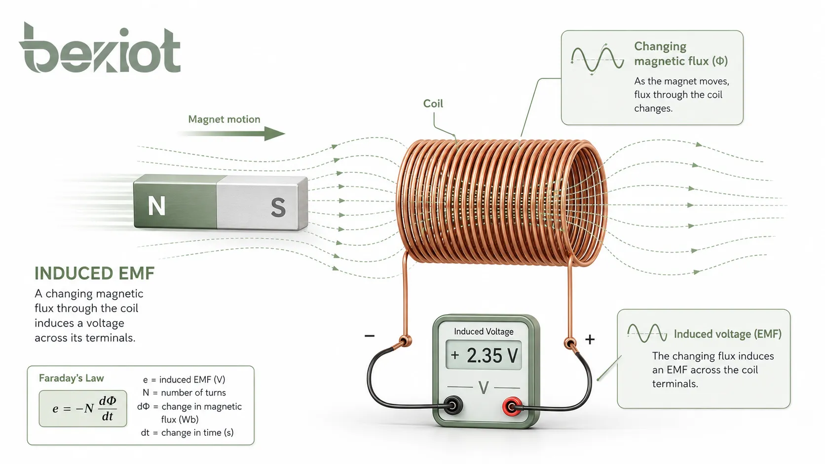
Induced EMF is the electrical result of changing magnetic flux. It is the reason motion, changing fields, and rotating coils can be converted into usable voltage.
Induced EMF appears when the magnetic flux linked with a coil changes over time.
The Principle Behind Electromagnetic Induction
Electromagnetic induction happens when a conductor experiences a changing magnetic environment. This change may come from a magnetic field that increases or decreases, a conductor moving through a magnetic field, a coil rotating inside a magnetic field, or a changing angle between the field and the loop area.
Magnetic flux describes how much magnetic field passes through a surface. If the field strength, loop area, angle, or relative motion changes, the flux linked with the circuit also changes. That changing flux is what produces induced EMF.
A coil with more turns can produce a higher induced voltage because every turn links with the changing flux. When the induced effects from all turns are added together, the total EMF becomes larger. This is why transformers, generators, and inductors often use multiple turns of wire rather than a single loop.
Faraday’s Law in Practical Terms
Faraday’s law states that the induced EMF in a circuit is proportional to the rate of change of magnetic flux linkage. In everyday engineering language, this means a faster flux change produces a higher voltage, and a coil with more turns produces a stronger induced EMF.
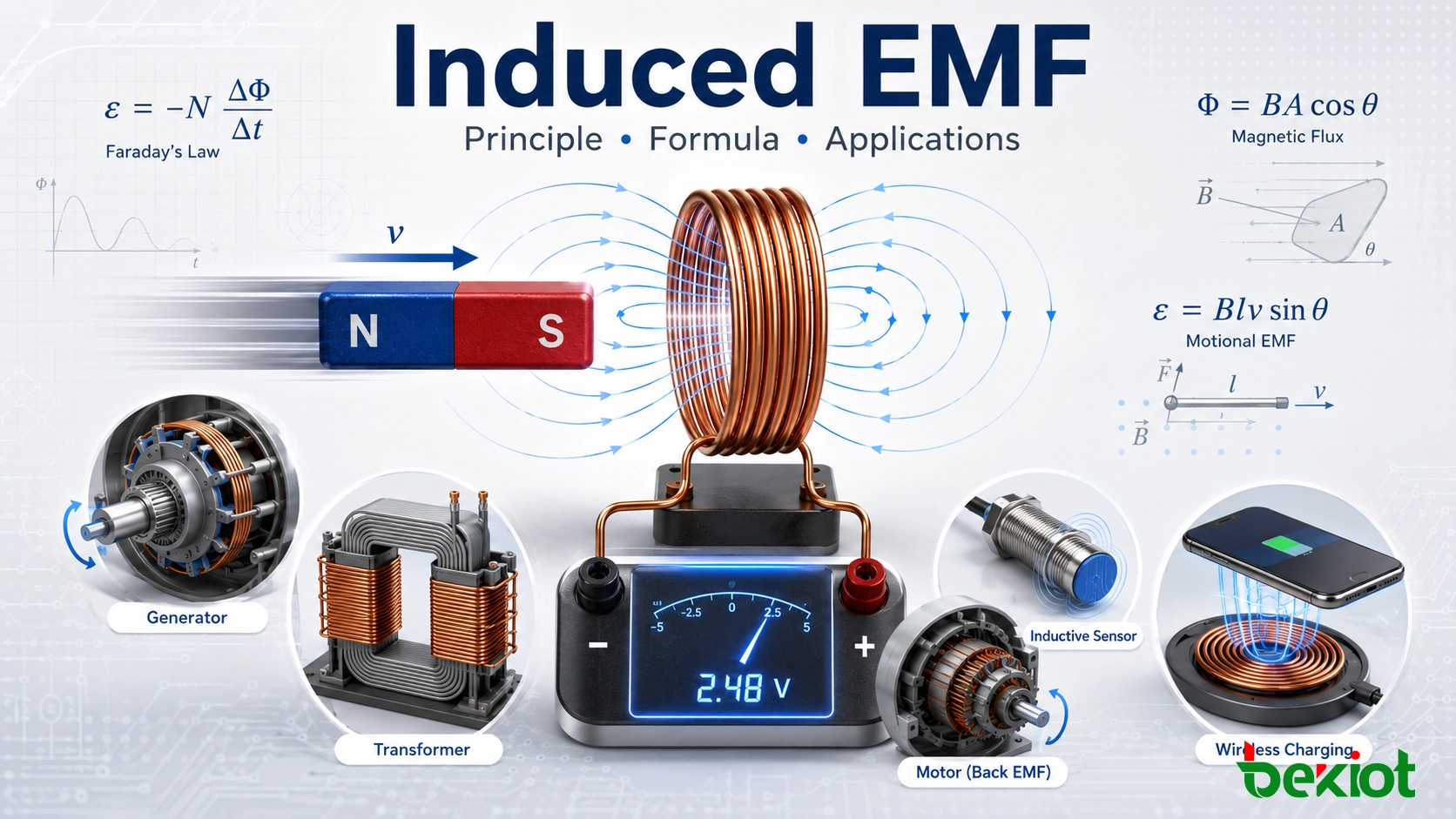
This principle is used in many systems. In a generator, mechanical rotation changes the flux linked with the coil. In a transformer, alternating current creates changing magnetic flux in the core. In an inductive sensor, movement or position changes the magnetic field pattern and creates a measurable electrical signal.
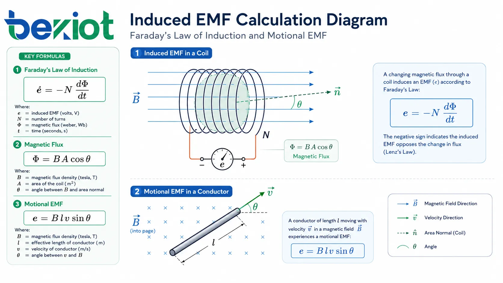
Faraday’s law is usually written as:
ε = -N × ΔΦ / Δt
In this formula, ε is the induced EMF in volts, N is the number of turns in the coil, ΔΦ is the change in magnetic flux in webers, and Δt is the time interval in seconds. The negative sign represents Lenz’s law, which describes the direction of the induced voltage.
When only the magnitude is needed, engineers often use:
|ε| = N × |ΔΦ| / Δt
Magnetic Flux and Its Formula
Magnetic flux is not the same as magnetic field strength. Flux depends on the magnetic flux density, the area through which the field passes, and the angle between the field and the surface. The standard formula is:
Φ = B × A × cosθ
Here, Φ is magnetic flux in webers, B is magnetic flux density in teslas, A is area in square meters, and θ is the angle between the magnetic field and the normal line perpendicular to the coil surface.
Flux is maximum when the magnetic field passes straight through the coil surface. It becomes zero when the magnetic field is parallel to the surface because no field passes through the loop area. This relationship is important in rotating machines, sensors, and transformer core design.
How Induced Voltage Is Produced
Induced voltage can be produced in several ways. The physical setup may change, but the underlying idea remains the same: magnetic flux linked with the conductor or coil must change.
Changing the Magnetic Field Around a Coil
If a coil is placed near a magnetic field that changes over time, voltage is induced in the coil even when the coil does not move. This is the working principle of transformers, inductors, current transformers, wireless charging coils, electromagnetic pickups, and many measuring devices.
In these systems, the changing magnetic field is usually created by alternating current or another time-varying magnetic source. The faster the field changes, the larger the induced voltage can become.
Moving a Conductor Through a Magnetic Field
When a straight conductor moves through a magnetic field, free charges inside the conductor experience magnetic force. This separates charges along the conductor and creates a voltage difference. This type of induced voltage is called motional EMF.
The common motional EMF formula is:
ε = B × l × v × sinθ
In this formula, B is magnetic flux density, l is the effective conductor length, v is velocity, and θ is the angle between the direction of motion and the magnetic field. If the conductor moves perpendicular to the field, sinθ = 1, so the formula becomes ε = B × l × v.
Rotating a Coil in a Magnetic Field
Generators often use rotational motion. As the coil rotates inside a magnetic field, the angle between the coil and the field changes continuously. This produces a changing flux and generates alternating EMF.
When the coil rotates faster, the rate of flux change increases. This can raise the generated voltage and affect the output frequency, depending on the generator design. This principle is used in alternators, AC generators, bicycle dynamos, and many energy conversion devices.
Why Lenz’s Law Matters
Lenz’s law explains the direction of induced EMF and induced current. It states that the induced current flows in a direction that opposes the change in magnetic flux that produced it. This is why Faraday’s law includes a negative sign.
This opposition is not just a mathematical convention. It reflects conservation of energy. If the induced current helped the original change instead of opposing it, the system would be creating energy without input. In real machines and circuits, energy must come from mechanical work, electrical input, or another source.
Direction is important in motors, generators, transformers, relays, inductive braking, and protection circuits. Winding direction, polarity marks, phase relationships, and terminal labels all matter when coils and magnetic systems are connected in practical equipment.
Back EMF in Electric Motors
Back EMF is a familiar example of induced EMF in motors. When a motor rotates, its windings move through a magnetic field and generate a voltage that opposes the applied supply voltage. This opposing voltage helps limit the current during normal operation.
At startup, the motor speed is low, so back EMF is also low. This can allow a high starting current. As the motor accelerates, back EMF increases and reduces the effective voltage driving current through the winding. This behavior is important for motor control, efficiency, protection, and speed regulation.
Faraday’s law, magnetic flux, and motional EMF formulas are used for different induction situations.
Key Symbols and Units
Before solving induced EMF problems, it is useful to identify each symbol and unit. Correct units help prevent common calculation errors.
Symbol
Meaning
Common Unit
ε
Induced electromotive force
Volt, V
N
Number of coil turns
Turns
Φ
Magnetic flux
Weber, Wb
B
Magnetic flux density
Tesla, T
A
Area linked by the magnetic field
Square meter, m²
l
Effective conductor length
Meter, m
v
Conductor velocity
Meter per second, m/s
t
Time
Second, s
Step-by-Step Calculation Examples
Induced EMF calculations become much easier when the physical situation is identified first. A changing flux through a coil uses Faraday’s law. A moving conductor in a magnetic field uses the motional EMF formula. A problem involving field strength, area, and angle may require magnetic flux to be calculated before EMF is found.
Example One: Coil with Changing Magnetic Flux
A coil has 200 turns. The magnetic flux through each turn changes from 0.06 Wb to 0.02 Wb in 0.5 seconds. What is the average induced EMF?
The flux change is:
ΔΦ = 0.02 - 0.06 = -0.04 Wb
The magnitude of the change is 0.04 Wb. Using Faraday’s law:
|ε| = N × |ΔΦ| / Δt = 200 × 0.04 / 0.5 = 16 V
The average induced EMF is 16 volts. The polarity depends on the direction of flux change and the winding direction.
Example Two: Moving Conductor
A straight conductor with an effective length of 0.5 m moves at 3 m/s through a magnetic field of 0.8 T. The motion is perpendicular to the magnetic field. What is the induced EMF?
Since the conductor moves perpendicular to the field, sinθ = 1.
ε = B × l × v = 0.8 × 0.5 × 3 = 1.2 V
The induced EMF is 1.2 volts. If the conductor moved at a smaller angle to the field, the induced voltage would be lower.
Example Three: Magnetic Flux from Area and Angle
A coil has an area of 0.02 m² and is placed in a magnetic field of 0.5 T. The magnetic field is perpendicular to the coil surface. What is the magnetic flux?
When the field is perpendicular to the surface, the angle between the field and the area normal is 0°, so cos0° = 1.
Φ = B × A × cosθ = 0.5 × 0.02 × 1 = 0.01 Wb
If this flux changes over time, Faraday’s law can then be used to calculate the induced EMF.
What Changes the Induced Voltage
Several factors determine how much EMF is induced. These factors are important when designing generators, transformers, inductive sensors, wireless charging coils, magnetic pickups, and other electromagnetic systems.
Rate of Flux Change
The faster the magnetic flux changes, the larger the induced EMF becomes. A rapidly moving magnet can induce a higher voltage than a slowly moving magnet in the same coil. In AC systems, higher frequency can also increase induced voltage because the flux changes more quickly.
Number of Coil Turns
More turns usually produce a higher induced voltage because each turn contributes to the total flux linkage. However, more turns can also increase resistance, winding size, capacitance, insulation demand, and heat. Practical designs must balance voltage output with losses, current capacity, and physical space.
Magnetic Field Strength
A stronger magnetic field can increase magnetic flux and therefore produce a larger induced EMF. Stronger magnets, suitable magnetic cores, and optimized air gaps can improve induction performance. At the same time, core saturation, hysteresis, eddy currents, and heating must be considered.
Area and Orientation
A larger loop area can link more magnetic flux. The orientation of the loop also matters. If the loop is positioned so that more field passes through it, the induced voltage can be higher when the field changes. In rotating machines, the changing angle between the coil and field is exactly what creates alternating EMF.
Where Induced EMF Is Used
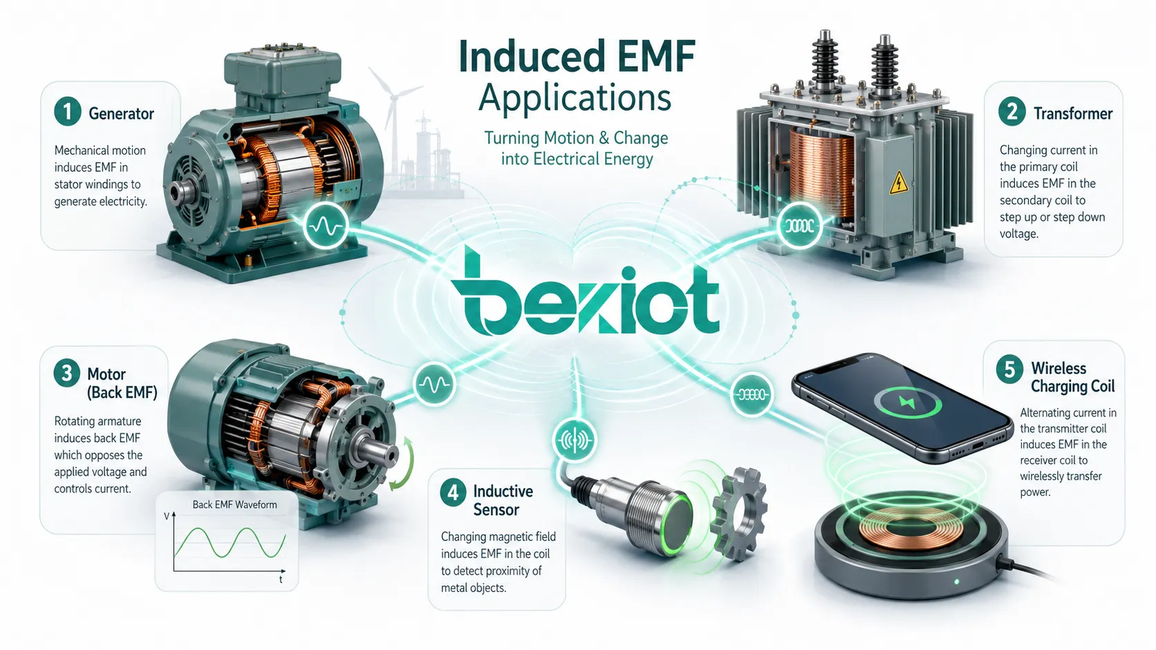
Induced EMF is not only a textbook concept. It is a foundation of power generation, voltage conversion, motion detection, electromagnetic sensing, wireless power transfer, and motor control.
Generators and Alternators
Generators convert mechanical energy into electrical energy through electromagnetic induction. A conductor or coil moves relative to a magnetic field, creating changing flux linkage and generating voltage. Large power station generators, vehicle alternators, portable generators, and bicycle dynamos all rely on this principle.
Transformers and Power Supplies
Transformers use changing magnetic flux to transfer energy between windings. Alternating current in the primary winding creates a changing magnetic field in the core, which induces voltage in the secondary winding. The voltage ratio depends mainly on the turns ratio between the windings.
Motors and Drive Systems
Motors generate back EMF during rotation. This induced voltage affects current, speed, torque, and control behavior. Brushless DC motors, sensorless drives, servo systems, and industrial motor controllers often use back EMF information for monitoring and control.
Sensors and Measurement Devices
Inductive sensors, magnetic pickups, current transformers, tachometers, metal detectors, and some flow meters use induced EMF to convert motion, position, current, or magnetic field change into an electrical signal. These devices are useful in non-contact measurement and industrial automation.
Wireless Charging
Wireless charging uses a changing magnetic field to induce voltage in a receiver coil. A transmitter coil creates alternating magnetic flux, and the receiver coil converts part of that energy into electrical output. Efficiency depends on coil alignment, distance, frequency, magnetic design, and load control.
Induced EMF is used in generators, transformers, motors, sensors, and wireless charging systems.
Practical Design and Measurement Notes
Real electromagnetic systems are affected by more than ideal formulas. Resistance, leakage flux, load current, core losses, eddy currents, capacitance, temperature, waveform shape, and mechanical tolerances can all change the measured output.
Open-Circuit EMF and Loaded Voltage
The voltage predicted by Faraday’s law often represents generated EMF before internal drops and load effects are considered. Once a load is connected, current flows and the terminal voltage may be lower. This difference is important in generators, transformers, sensors, and power devices.
Eddy Currents and Heat Loss
Changing magnetic fields can induce circulating currents inside conductive materials. These eddy currents can cause heating and energy loss in transformer cores, motor laminations, generator parts, and nearby metal structures. Laminated cores and ferrite materials are often used to reduce these losses.
Choosing the Right Measuring Instrument
Induced EMF can be measured with a voltmeter, oscilloscope, data acquisition system, or specialized analyzer. For steady or low-frequency signals, a multimeter may be enough. For fast-changing, pulsed, or non-sinusoidal signals, an oscilloscope is often better because it shows waveform shape, peak value, timing, and transient behavior.
Common Calculation Mistakes
A frequent mistake is using magnetic flux density directly in Faraday’s law without calculating magnetic flux. If a problem gives B, A, and θ, calculate Φ = B × A × cosθ first, and then use the change in flux to find induced EMF.
Another mistake is forgetting the number of turns. For a coil, the total induced EMF depends on flux linkage, so the number of turns must be included unless the problem clearly refers to a single loop.
Direction and polarity can also cause confusion. If only magnitude is required, the negative sign in Faraday’s law is often omitted. If the problem asks for polarity or current direction, Lenz’s law must be used.
In AC systems, voltage values should also be checked carefully. Peak voltage, average voltage, and RMS voltage are not the same. RMS values are commonly used in practical AC power systems, while peak values are common in waveform analysis.
Summary
Induced EMF is the voltage produced when magnetic flux linked with a conductor or coil changes. It can be generated by a changing magnetic field, a moving conductor, or a rotating coil. Faraday’s law gives the magnitude of induced EMF, while Lenz’s law explains its direction.
The amount of induced voltage depends on flux change rate, coil turns, magnetic field strength, loop area, orientation, conductor speed, and system design. In real equipment, losses, load effects, heat, materials, and measurement conditions must also be considered.
From generators and transformers to motors, sensors, magnetic pickups, current transformers, and wireless charging, induced EMF is one of the most important principles behind electrical energy conversion and electromagnetic signal generation.
FAQ
What is induced EMF in simple words?
Induced EMF is the voltage created when a conductor or coil experiences a changing magnetic flux. It may happen when a magnetic field changes, when a conductor moves through a magnetic field, or when a coil rotates in a magnetic field.
Does induced EMF always create current?
No. Induced EMF creates voltage. Current flows only when there is a closed conducting path. In an open circuit, voltage can appear across terminals, but continuous current cannot flow.
What is the difference between induced EMF and terminal voltage?
Induced EMF is the generated voltage before considering internal losses and load effects. Terminal voltage is the voltage actually available at the output terminals, which may be lower when current flows through a load.
Why does a motor create back EMF?
A rotating motor winding cuts magnetic field lines and generates an induced voltage. This voltage opposes the supply voltage and is called back EMF. It helps limit current during normal operation.
Which formula should be used for a moving conductor?
For a straight conductor moving through a magnetic field, use ε = B × l × v × sinθ. If the conductor moves perpendicular to the field, the formula becomes ε = B × l × v.