Low-Voltage Installation Guide for Safe Wiring, Testing, and Acceptance
A practical guide to low-voltage installation, covering project scope, cable routing, panel wiring, grounding, protection devices, pre-energization testing, acceptance standards, handover documents, and long-term maintenance.
Becke Telcom
Low-voltage installation covers the design, wiring, protection, testing, and acceptance of electrical systems used in buildings, industrial facilities, commercial spaces, public infrastructure, control rooms, data rooms, equipment rooms, and related technical areas. It may include power distribution, lighting circuits, control wiring, grounding, cable trays, conduits, distribution panels, protective devices, terminal connections, cabinets, and auxiliary electrical systems.
The term “low voltage” can sound less dangerous than high-voltage power work, but poor installation can still cause electric shock, overheating, fire risk, nuisance tripping, equipment damage, unstable operation, communication interference, and difficult maintenance. A reliable low-voltage project depends on clear scope definition, correct material selection, qualified installation, systematic testing, and acceptance based on approved standards.
For engineers, contractors, facility managers, and project owners, low-voltage installation should not be treated as simple cable pulling. It is a complete process that connects design intent, site conditions, safety rules, workmanship, test results, documentation, and long-term maintainability.
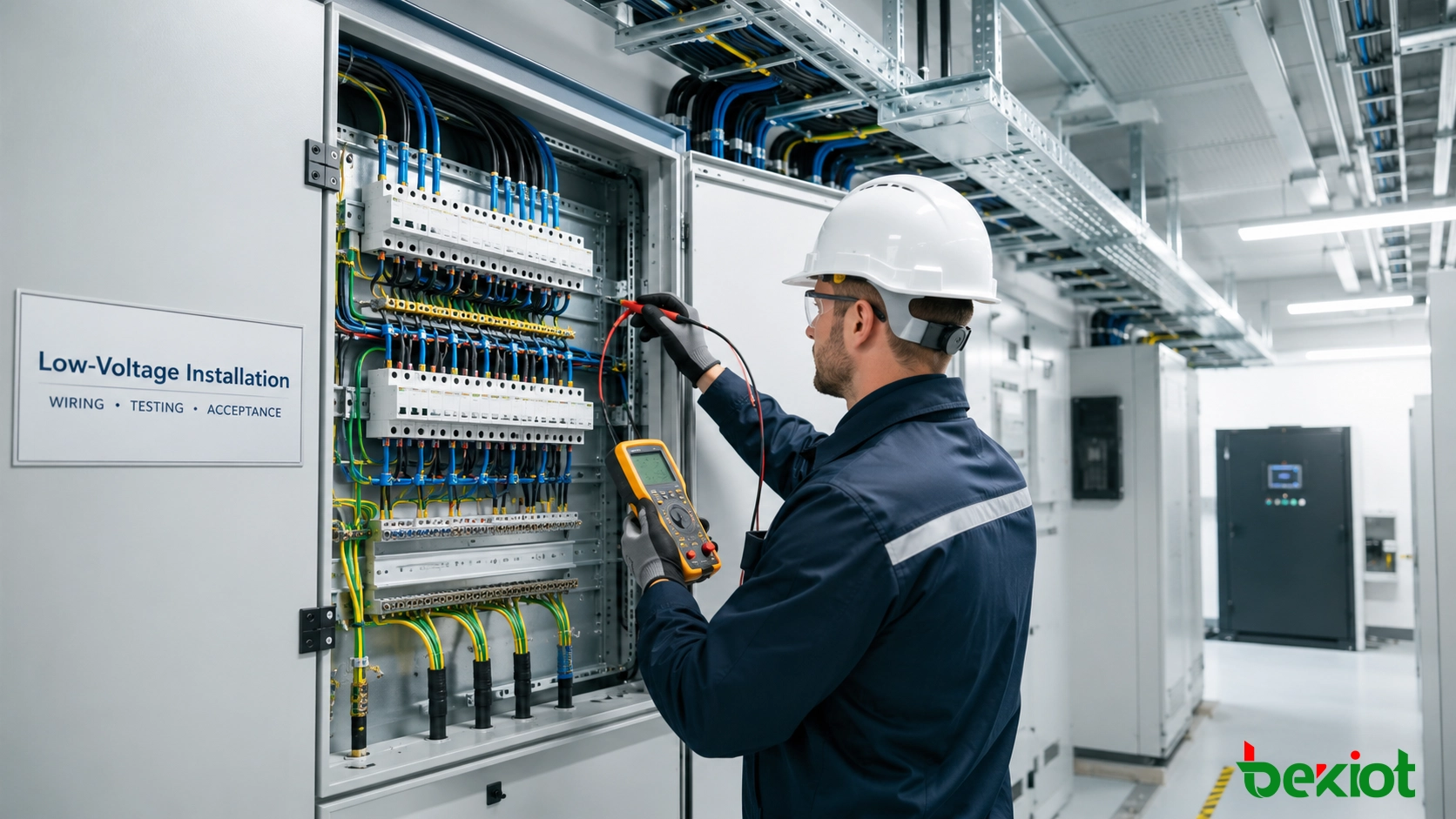
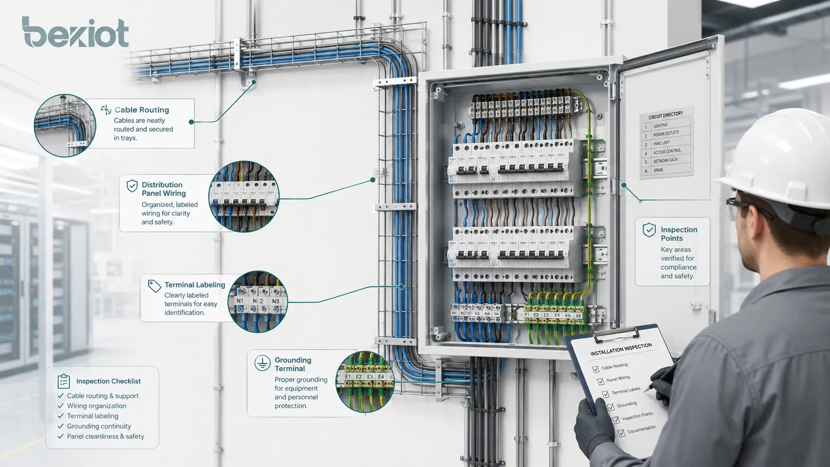
Low-voltage installation quality depends on correct cable routing, panel wiring, grounding, labeling, testing, and inspection throughout the project.
Define the Project Scope Before Installation
Before any installation work begins, the project team should define the technical scope clearly. In one project, low-voltage installation may refer to building electrical distribution and branch circuits. In another project, it may also include extra-low-voltage systems such as access control, CCTV, fire alarm interfaces, building automation, communication wiring, security systems, and control signal wiring.
This distinction is important because different systems may follow different standards, cable types, separation rules, grounding practices, and acceptance methods. The project team should confirm which systems are included, which drawings are approved, which standards apply, and where responsibility changes between electrical, mechanical, civil, communication, fire protection, and automation teams.
A clear scope avoids confusion during construction and acceptance. It also helps prevent common disputes such as missing cable routes, unclear interface points, wrong cable selection, incomplete panel schedules, or untested control circuits.
Standards, Drawings, and Site Conditions
Low-voltage installation should follow the legal and technical requirements of the project location. International standards, national electrical codes, local fire regulations, utility requirements, building codes, manufacturer instructions, and project specifications may all affect how the system is installed and accepted.
In many international projects, IEC-based practices may be used. In the United States and some related markets, NEC-based practices may apply. However, final acceptance should never rely on a generic article alone. The approved drawings, contract documents, authority requirements, inspection procedures, and certified test records should be treated as the project baseline.
Site conditions also change the installation method. A dry office building, wet basement, outdoor cabinet, chemical plant, tunnel, factory workshop, data center, or control room may require different cable protection, enclosure ratings, grounding design, corrosion resistance, fire-stopping treatment, and maintenance access.
Preparation Before Site Work
Good preparation prevents many defects later. Before installation, the team should review single-line diagrams, load schedules, cable schedules, panel layouts, grounding drawings, routing plans, equipment manuals, installation details, and interface drawings. Any conflict between drawings, equipment requirements, and actual site conditions should be clarified before work starts.
Materials should also be checked before installation. Cables, conduits, trays, breakers, residual current devices, panels, terminal blocks, busbars, meters, surge protective devices, labels, enclosures, glands, lugs, ferrules, and accessories should match the approved submittals. Their model, rating, certificate, quantity, and appearance should be verified.
Storage matters as well. Cables should be protected from moisture, crushing, sharp bending, and unsuitable direct sunlight. Panels and cabinets should be kept clean and dry before energization. Damaged, uncertified, or unapproved materials should not be installed simply to keep the schedule moving.
Tools, Personnel, and Work Sequence
Low-voltage installation should be carried out by qualified personnel using proper tools. Cable cutters, stripping tools, crimping tools, torque tools, insulation testers, multimeters, continuity testers, earth resistance testers, labeling machines, and personal protective equipment should be prepared according to the work type.
Incorrect tools can create hidden problems. Poor crimping, loose terminals, over-tightened lugs, scratched insulation, damaged conductor strands, and wrong stripping length may not be obvious during a quick visual check, but they can cause overheating, unstable operation, or failure after the system is energized.
Work sequencing should be coordinated with civil construction, HVAC, plumbing, fire protection, communication systems, automation, and interior finishing. Cable tray routes, wall openings, panel positions, floor penetrations, ceiling access, and equipment clearances should be confirmed in advance. A tray blocked by ductwork or a cabinet installed behind fixed furniture can become a long-term maintenance problem.
Cable Routing and Mechanical Protection
Cable routing affects safety, electromagnetic compatibility, service life, maintenance access, and appearance. A good route protects cables from mechanical damage, heat, moisture, corrosion, sharp edges, excessive bending, vibration, and interference from other systems.
Cable trays, conduits, and raceways should be installed firmly, aligned neatly, and supported at suitable intervals. Sharp edges should be removed or protected. Where cables pass through walls, floors, or fire-rated barriers, sleeves, seals, and fire-stopping materials should be installed according to the project requirements.
Cables should not be bent beyond the manufacturer’s minimum bending radius. Excessive bending can damage insulation, shielding, conductor structure, or cable geometry. During pulling, excessive force should be avoided. Long routes may require rollers, guide tools, pulling lubricant, staged pulling, or additional manpower to prevent cable damage.
Separation Between Power and Signal Lines
Power cables can generate electromagnetic interference that affects control, audio, video, communication, and data lines. In control rooms, industrial automation cabinets, public address systems, security systems, data rooms, and building management systems, cable separation is especially important.
Where power and signal cables run in the same area, the design should consider separation distance, shielding, metal conduit, grounding method, and crossing angle. When cables must cross, a right-angle crossing is usually preferred to reduce coupling. Long parallel runs should be avoided unless the design includes suitable protection.
Poor cable separation may not cause immediate failure, but it can create intermittent faults, noise, distorted signals, communication errors, unstable sensors, or interference in audio and video systems. These problems are often difficult to diagnose after the building is finished.
Wiring, Termination, and Panel Quality
Panel wiring is one of the clearest indicators of installation quality. Neat wiring is helpful, but neatness alone is not enough. Conductors must be correctly sized, identified, stripped, crimped, terminated, protected, and tested.
Phase conductors, neutral conductors, protective earth conductors, control wires, and signal wires should be identified according to the project standard. Color coding, labels, sleeves, ferrules, and wire tags should be consistent and readable. Accurate identification makes testing, troubleshooting, maintenance, and future modification safer.
Terminal tightness should be controlled carefully. Loose terminals can cause overheating, arcing, voltage drop, and intermittent faults. Over-tightening can damage threads, crush conductors, or weaken terminal hardware. Where manufacturer torque values are specified, torque tools and inspection marks should be used.
Panels should also allow enough room for wiring, ventilation, operation, inspection, and future maintenance. Equipment should not be overcrowded. Heat-generating devices need suitable clearance and airflow. Doors should open fully, labels should be visible, and live parts should be protected against accidental contact.
Grounding and Protective Bonding
Grounding and protective bonding are essential for electrical safety. They reduce electric shock risk, support automatic disconnection during faults, stabilize reference potential, and improve equipment reliability.
Required exposed conductive parts should be connected to the protective earth system. This may include distribution boards, metal enclosures, cable trays, control cabinets, metal conduits, equipment frames, motor bodies, and other conductive parts specified by the design.
A visual earth connection is not enough. Protective earth continuity should be tested before energization. Paint layers, corrosion, loose terminals, missing bonding jumpers, broken conductors, or disconnected tray sections can weaken the protective path.
Equipotential bonding is also important in wet areas, mechanical rooms, industrial sites, medical-related areas, and locations with large conductive structures. Bonding should follow approved drawings and applicable standards. Random grounding changes can create safety problems or electrical noise.
Protection Devices and Circuit Coordination
Low-voltage systems rely on protective devices to respond correctly during overloads, short circuits, leakage faults, surges, and abnormal conditions. Circuit breakers, fuses, residual current devices, and surge protective devices should match the cable size, load type, fault level, installation method, and coordination design.
The rating of a protective device should not be changed casually on site. Replacing a breaker with a higher rating to avoid tripping may create a fire risk if the cable or equipment cannot safely carry the current.
Residual current protection may be required for specific circuits or environments. Its rated residual operating current, type, response behavior, and coordination with upstream devices should follow the design. During acceptance, functional trip tests should be performed where applicable.
Surge protective devices may be needed for equipment exposed to lightning-induced surges, utility switching surges, long outdoor cable routes, sensitive electronics, communication interfaces, or automation systems. SPD performance depends not only on the device rating, but also on grounding path, conductor length, installation position, and coordination level.
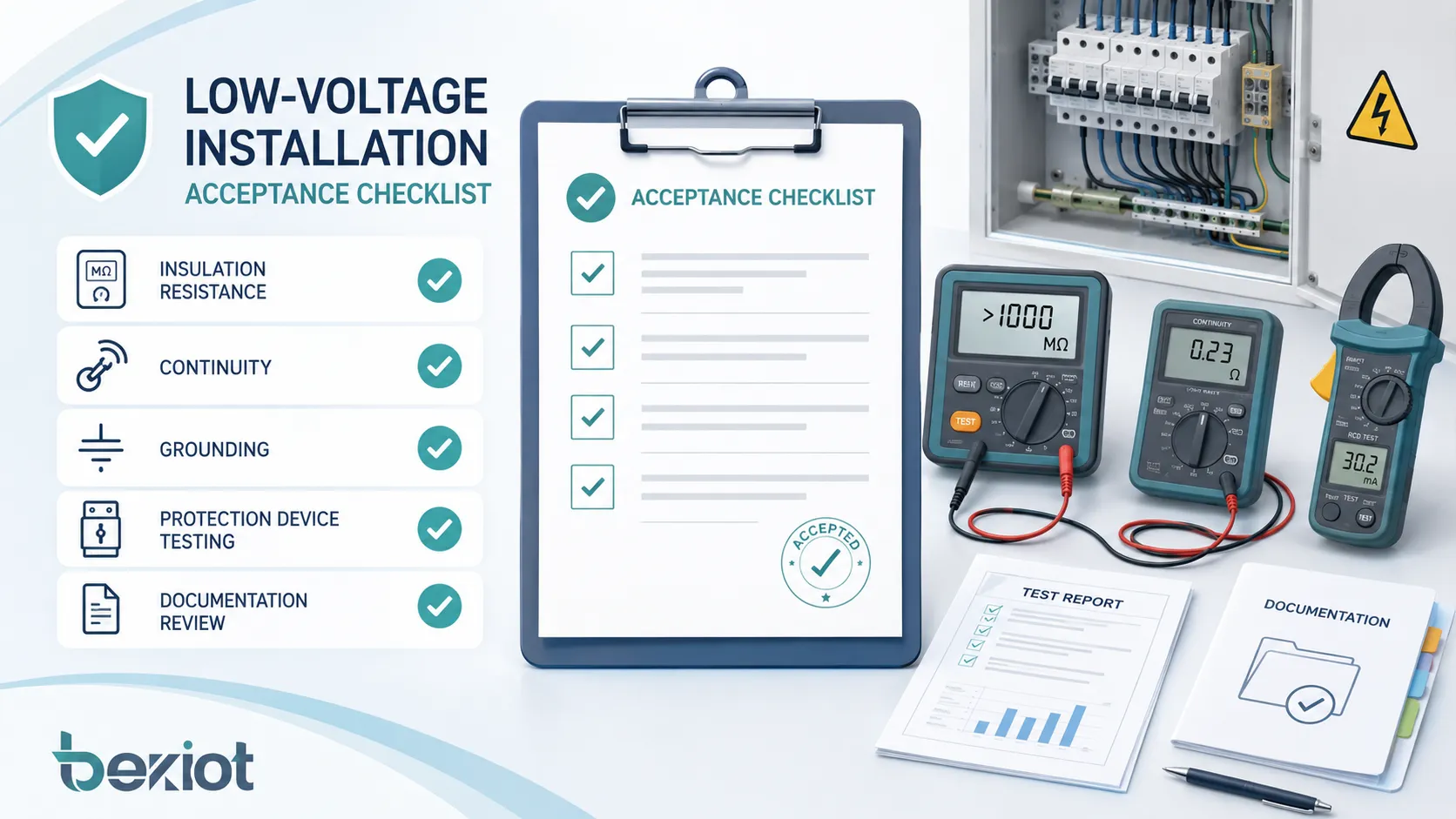
Acceptance testing should verify wiring correctness, grounding continuity, insulation resistance, protection device performance, functional operation, and documentation completeness.
Testing Before Energization
Testing before energization is a critical safety step. It helps identify wiring errors, damaged insulation, grounding problems, wrong phase sequence, loose connections, incorrect labels, and protective device issues before the system is powered.
Visual inspection should confirm that the installation matches approved drawings, equipment is securely installed, cable routes are complete, labels are present, panels are clean, terminals are tightened, covers are installed, and there is no visible damage. Temporary construction wiring should be removed, unused openings should be sealed, and access space should be clear.
Continuity testing verifies that protective conductors and bonding paths are properly connected. Insulation resistance testing helps confirm that conductors are not shorted, wet, damaged, or degraded. Test voltage and acceptance limits should follow applicable standards, equipment type, and project specifications. Sensitive electronic devices may need to be disconnected or protected before insulation testing.
Polarity checks confirm that live, neutral, and protective conductors are connected correctly. Phase sequence testing is important for three-phase motors, pumps, fans, compressors, and equipment that may rotate incorrectly if phases are reversed. Functional checks should verify switches, meters, indicators, interlocks, alarms, emergency stops, control circuits, and automatic transfer functions.
Acceptance Criteria for Low-Voltage Work
Acceptance should be based on the approved design, project specification, local code, applicable electrical standard, manufacturer instructions, authority inspection rules, and contract requirements. The following checklist provides a practical framework, but each project should adjust it according to its own scope.
Acceptance Item
Key Inspection Focus
Typical Requirement
Document review
Drawings, specifications, certificates, test records, as-built documents
Concealed work should be inspected before it is covered by walls, ceilings, floors, trenches, insulation, or finishes. This includes conduits, embedded boxes, cable routes, sleeves, fire-stopping materials, grounding conductors, and hidden junction points.
Once concealed, defects become difficult and expensive to correct. Photo records, inspection forms, measured routes, and signed acceptance records should be kept for future maintenance and final handover.
Panel acceptance should check enclosure installation, internal cleanliness, wiring neatness, conductor identification, terminal tightness, breaker rating, busbar arrangement, grounding connection, label accuracy, ventilation, door operation, locks, warning signs, and circuit matching with the panel schedule.
Safe Energization and Load Review
Energization should only occur after required inspections and tests are complete. The team should confirm that all personnel are clear, downstream equipment is ready, temporary grounds are removed, covers are installed, and switching authority is assigned.
For large projects, staged energization is often safer than powering the whole system at once. Each stage should be monitored for abnormal sound, smell, temperature, voltage, current, tripping, or warning signals.
After the system operates under load, the team should review voltage, current, phase balance, temperature rise, and abnormal heating. Thermal imaging can help detect hot terminals, overloaded conductors, or poor connections. This is especially useful for distribution panels, motor circuits, UPS outputs, server rooms, production equipment, and high-utilization circuits.
Documentation and Handover
Documentation is part of acceptance. Without complete records, future maintenance teams may not know how the system was installed, tested, modified, or approved.
As-built drawings should reflect the actual installation. They should show final cable routes, panel numbers, circuit numbers, equipment locations, grounding points, junction boxes, spare conduits, and approved site changes. Drawings that do not match the site can create safety risks during maintenance and renovation.
Test reports should include test date, tested circuit, instrument model, calibration status where required, test method, test value, inspector name, witness name, and final result. Material certificates, equipment manuals, breaker settings, panel schedules, warranty documents, spare part information, and operation instructions should also be included in the handover package.
For 24-hour facilities, operators should receive training on normal switching, emergency isolation, alarm recognition, reset procedures, maintenance reporting, and safe operation boundaries.
Common Defects Found During Acceptance
Many low-voltage installation defects are repetitive. Missing or inaccurate labels are among the most common issues. A panel may look neat, but if circuit numbers and destination labels are wrong, maintenance becomes risky. Acceptance should verify whether the actual circuit destination matches the panel schedule and as-built drawing.
Loose connections and damaged conductors are also serious defects. Loose terminals, poorly crimped lugs, exposed copper, broken strands, damaged insulation, and incorrect stripping length can cause overheating, arcing, voltage drop, or intermittent faults.
Grounding defects are often hidden. Missing bonding jumpers, painted contact surfaces, loose earth terminals, undersized conductors, and disconnected cable tray sections may weaken the protective earthing system. Continuity testing and visual checks are essential before acceptance.
Acceptance Should Consider Long-Term Maintenance
A good low-voltage installation should not only pass initial inspection. It should also be easy to operate, maintain, troubleshoot, and expand over many years. Panels, junction boxes, cable trays, isolators, and test points should remain accessible. Equipment should not be blocked by fixed furniture, piping, ductwork, stored materials, or architectural finishes.
Spare capacity should be checked if the design includes future expansion. Spare breakers, spare terminals, spare conduits, cable tray reserve capacity, and panel space are useful only if they are preserved during construction. If spare capacity is lost, future upgrades may become expensive.
For commercial buildings, industrial plants, data rooms, and technology spaces, future load growth should be reviewed carefully. A system that works on day one may become overloaded if expansion planning is ignored.
Summary
Low-voltage installation is a complete engineering process that includes scope confirmation, material checking, cable routing, termination, grounding, protection coordination, testing, acceptance, documentation, and maintenance planning. Although the voltage level is lower than high-voltage systems, installation quality directly affects electrical safety, equipment reliability, fire prevention, and long-term operation.
A dependable project should be built on approved drawings, qualified workmanship, correct protective devices, reliable grounding, proper cable protection, complete testing, and clear handover documents. Acceptance should not only ask whether the system can be energized. It should also confirm whether the system is safe, traceable, maintainable, and ready for real operation.
FAQ
What is included in low-voltage installation?
It may include distribution boards, branch circuits, lighting circuits, control wiring, grounding, cable trays, conduits, protection devices, panels, cabinets, terminal connections, and related auxiliary systems. The exact scope depends on the project definition.
What should be checked before installation starts?
The team should check approved drawings, cable schedules, panel schedules, material certificates, equipment ratings, site conditions, installation routes, environmental requirements, safety procedures, and coordination with other disciplines.
Why is insulation resistance testing important?
Insulation resistance testing helps identify damaged, wet, shorted, or degraded conductors before energization. It reduces the risk of faults, equipment damage, and unsafe operation.
What documents are usually needed for acceptance?
Acceptance documents usually include approved drawings, as-built drawings, test reports, inspection records, material certificates, equipment manuals, commissioning records, panel schedules, operation instructions, and maintenance information.
Why should concealed work be inspected early?
Concealed work becomes difficult to inspect or repair after walls, ceilings, floors, trenches, or finishes are completed. Early inspection helps confirm cable routes, conduits, fire-stopping, grounding, and hidden junction points before they are covered.