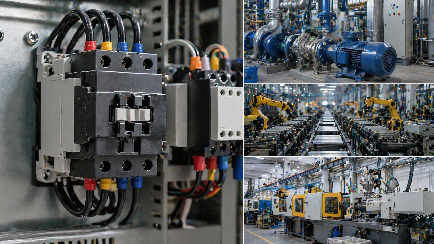
An AC contactor is an electrically controlled switch used to connect and disconnect power to motors, pumps, compressors, heaters, lighting banks, and other industrial loads. In a control panel, it separates the power circuit from the control circuit: the main contacts carry load current, while the coil and auxiliary contacts let push buttons, relays, PLC outputs, or protection devices start and stop the load safely.
An AC contactor wiring diagram shows how these pieces tie together. A typical diagram identifies the incoming line terminals, outgoing load terminals, coil terminals, overload relay, start and stop devices, and any auxiliary contacts used for interlocking or seal-in control. Reading this structure correctly matters for installation, maintenance, fault tracing, and safe panel design.
Wiring a contactor is more than attaching conductors to labeled terminals. The right arrangement depends on coil voltage, load type, control voltage source, short-circuit protection, overload protection, and the manufacturer's exact schematic. General wiring principles get you started, but the final installation always follows the device datasheet and the project drawing.
General diagrams are useful for understanding the logic of a contactor circuit, but the final installation must follow the exact terminal layout, coil rating, and protection requirements of the specific device being used.
A basic AC contactor installation combines a power path for the load with a lower-power control path for the coil and operating logic.
What an AC Contactor Wiring Diagram Shows
Power Terminals and Load Terminals
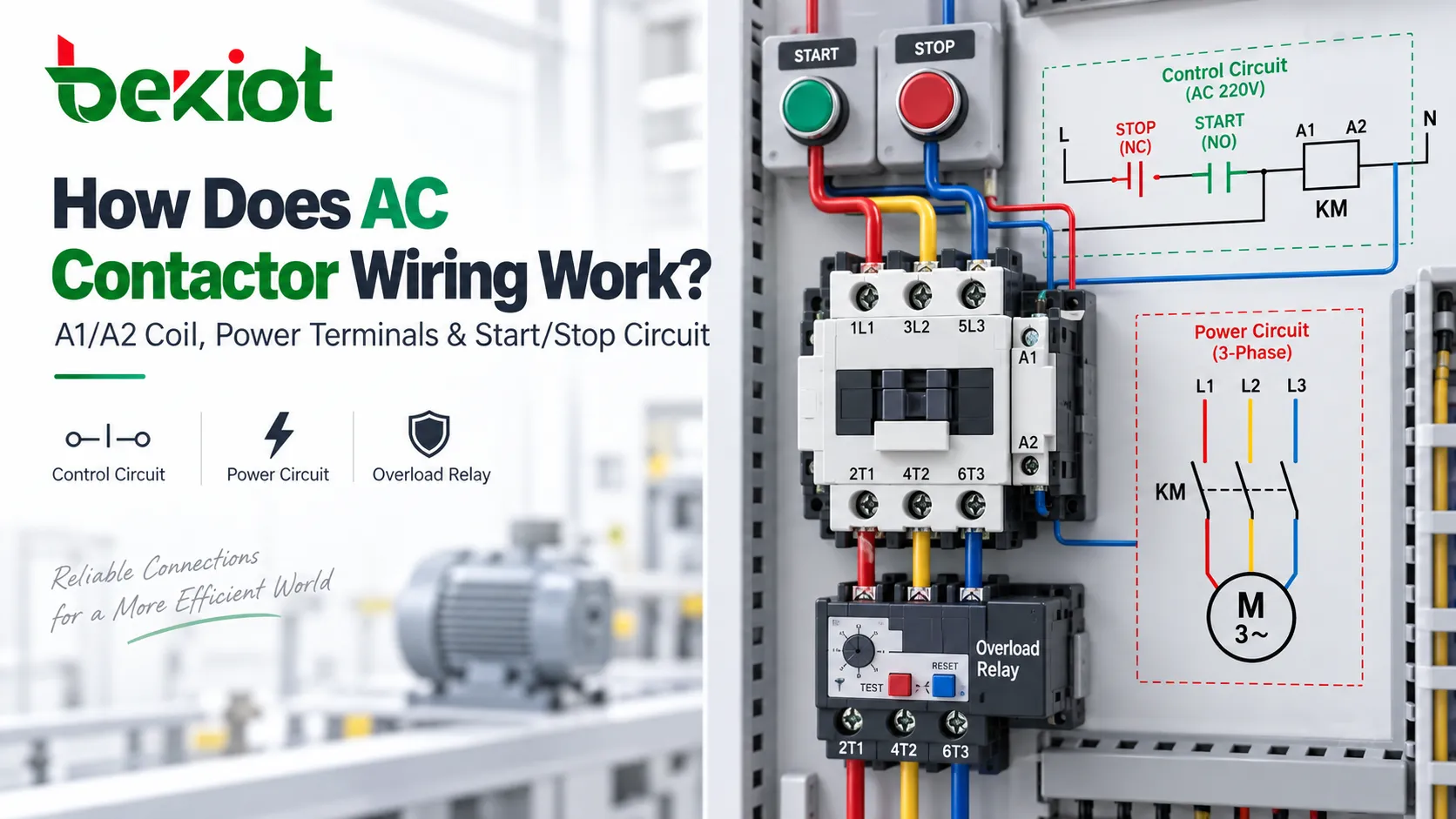
The first part of the diagram is the main power path. On many IEC-style contactors, the incoming supply is marked on the line side with 1L1, 3L2, and 5L3, while the outgoing side is marked 2T1, 4T2, and 6T3. When the coil energizes, the main contacts close and connect line side to load side; when the coil drops out, those contacts open and disconnect the load.
In a three-phase motor starter, these poles feed the overload relay and then the motor. In smaller or single-phase applications, the contactor may use fewer poles, but the logic is the same: line power enters on the source side and exits on the load side only when the contactor is pulled in.
The power circuit and the control circuit should always be read separately. The heavy-current path tells you how the load is switched; the control path tells you what makes the contactor open or close.
Coil Terminals and Auxiliary Contacts
The second part of the diagram is the control circuit. On most contactors the coil terminals are A1 and A2. Applying the correct control voltage across these two terminals energizes the coil and changes the contactor state. For AC coils the main concern is matching the coil to the rated control voltage; DC-coil models may also mark polarity.
Contactors usually add auxiliary contacts as well. A common pair is a normally open auxiliary contact marked 13/14 and a normally closed one marked 21/22. These contacts do not carry motor or heater current. They live in the control circuit for feedback, interlocking, indication, or hold-in logic.
In a standard three-wire start/stop circuit, the normally open auxiliary contact is wired in parallel with the start push button to form a seal-in or holding path. Once the coil pulls in and that auxiliary contact closes, the contactor stays energized after the start button is released, until a stop button or protection contact opens the circuit.
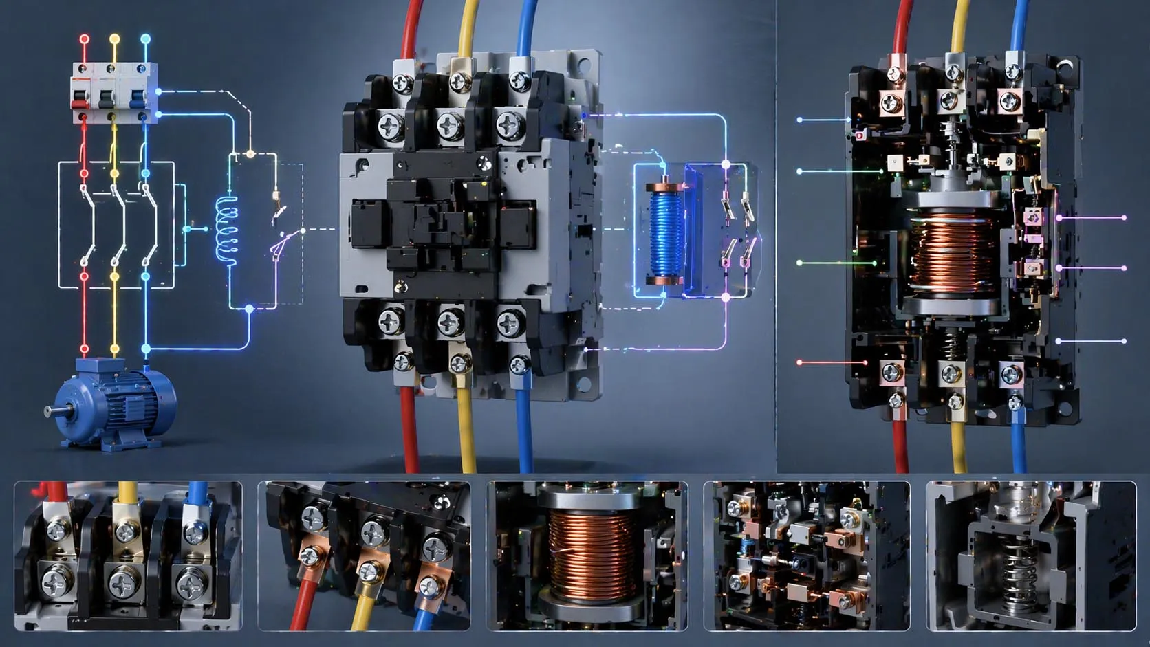
Most wiring diagrams start with terminal identification so the installer can tell coil, power, and auxiliary functions apart at a glance.
Basic Working Principle of an AC Contactor Circuit
How the Coil Operates the Main Contacts
The operating principle is straightforward. When the control circuit sends the rated voltage to A1 and A2, the electromagnetic coil pulls in the moving contact assembly, closing the main contacts and, depending on the design, changing the auxiliary contacts at the same time. Remove coil power and spring force returns the contactor to its normal state.
This lets a low-power control signal switch a much higher-power load. Motors and other equipment can be started from push-button stations, thermostats, PLC outputs, timer relays, safety relays, float switches, or remote devices without sending full load current through those control components.
Because the coil is the operating element, the control circuit needs the same care as the power circuit. Wrong coil voltage leads to chattering, overheating, failure to pull in, or permanent damage.
How a Standard Start/Stop Circuit Is Built
A common contactor wiring method uses a normally closed stop button, a normally open start button, the normally closed overload relay auxiliary contact, and a normally open auxiliary holding contact. In basic logic, control power flows through the stop contact and the overload contact, then through the start button to A1; A2 returns to the other side of the control supply.
Press the start button and the coil energizes. The auxiliary holding contact closes at the same time, creating a parallel path around the start button, so the contactor stays in after the button is released. Press the stop button, or trip the overload relay, and the control path opens — the contactor drops out.
This control method is widely used because it is simple, reliable, and easy to troubleshoot. It also splits operator control, overload protection, and load switching into clearly defined parts of the circuit.
A contactor does not protect the motor by itself. In most motor circuits, short-circuit protection and overload protection must be added separately and coordinated with the contactor rating.
Typical AC Contactor Wiring Steps
Step 1: Confirm the Device Rating and Coil Voltage
Before any wiring starts, confirm the contactor type, coil voltage, pole arrangement, current rating, utilization category, and any accessory modules such as auxiliary blocks or mechanical interlocks. Coil voltage deserves special attention because control circuits may run on 24 V AC, 24 V DC, 110 V AC, 120 V AC, 220–240 V AC, or other values depending on the panel design.
This is also the stage to check whether an overload relay mounts directly to the contactor and whether a control transformer, PLC relay output, selector switch, timer, or interlock contact is part of the design.
Step 2: Mount the Contactor and Related Devices
Mount the contactor per the manufacturer's instructions, usually on DIN rail or a panel backplate. Lay out the overload relay, terminal blocks, push buttons, protection devices, and wire ducts so line wiring, load wiring, and control wiring stay clear and serviceable.
Good panel layout is part of good wiring practice. Physical separation between power conductors and control conductors improves maintenance, reduces wiring errors, and makes future troubleshooting faster. It also helps heat management and keeps cable routing clean inside the enclosure.
Step 3: Wire the Main Power Circuit
After safe isolation and verification, connect the main supply conductors to the incoming line terminals of the contactor, and the outgoing conductors from the contactor or overload relay to the load. In many motor starter arrangements, line enters the contactor first, the load side feeds the overload relay, and the overload relay then feeds the motor terminals.
Conductor size, terminal torque, protection coordination, and phase sequence all follow the equipment documentation and local electrical code. The goal is not just to complete the path, but to complete it in a way that matches the rated application of the starter assembly.
Step 4: Wire the Control Circuit
Next comes the control circuit. A simple example runs from the control supply through the normally closed stop button, then through the normally closed overload relay auxiliary contact, then through the normally open start button, and finally to A1. A2 returns to the opposite leg of the control supply.
In a three-wire control method, the contactor's normally open auxiliary contact goes in parallel with the start button to form the holding circuit. Indicator lamps, interlocks, timer contacts, or PLC permissives are inserted according to the control sequence on the schematic.
This is where wiring discipline matters most. One misplaced auxiliary contact or one wrong control-voltage return can make the circuit fail to start, fail to hold, or fail to stop.
Step 5: Inspect, Test, and Commission
Before energizing, check every termination against the drawing and torque each terminal to specification. Verify wire identification, insulation condition, grounding, phase continuity, overload settings, and the mechanical freedom of the contactor and overload assembly.
Start commissioning with control-circuit checks and no-load or controlled-load testing where possible. Confirm that the stop function drops out the contactor, the start function latches correctly when a holding circuit is used, and the overload trip path opens the control circuit as intended. Final testing also looks for chatter, abnormal noise, overheating, or incorrect rotation on motor applications.
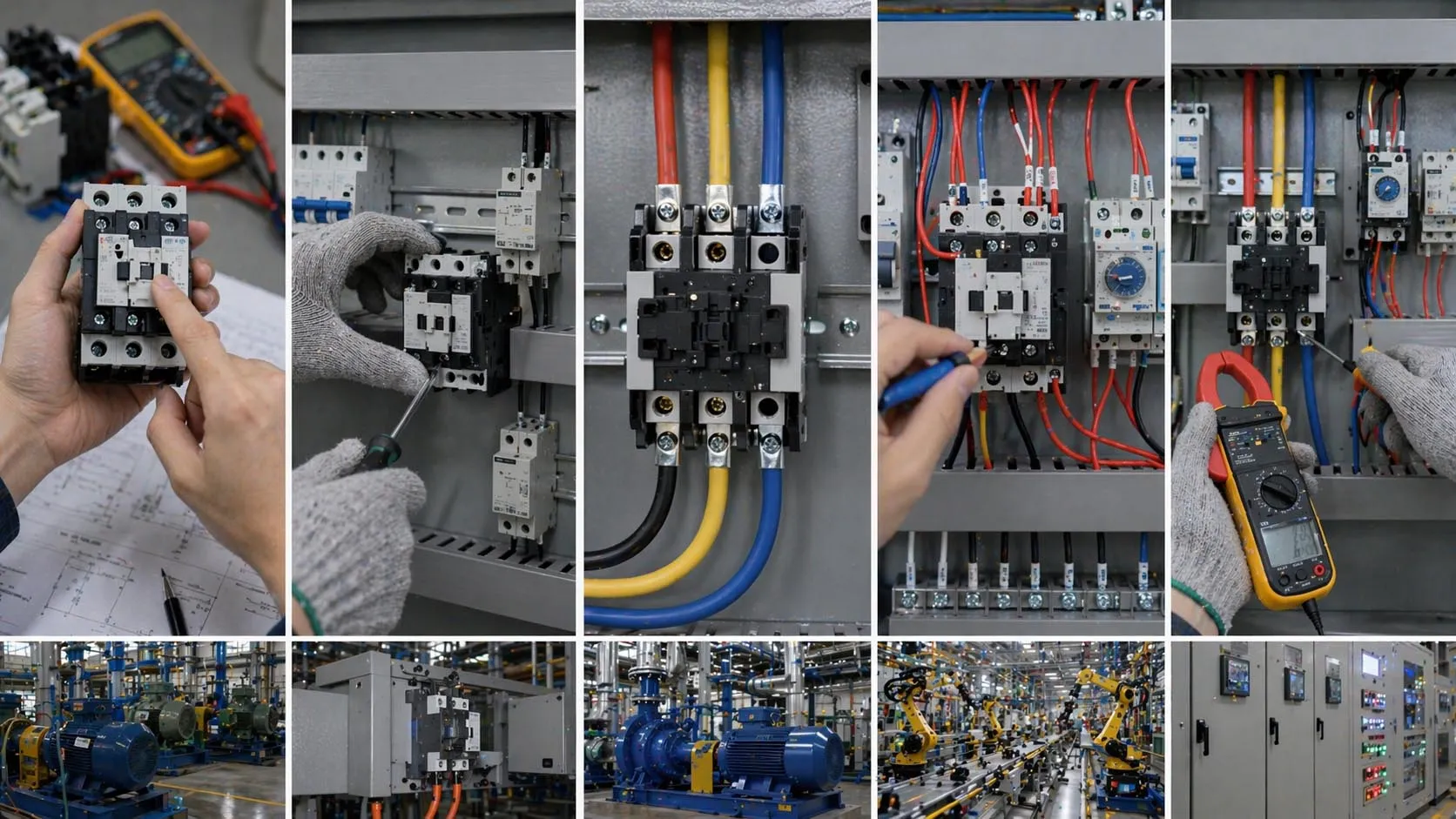
A successful installation depends on more than terminal connections — it also requires rating checks, layout discipline, inspection, and controlled commissioning.
Common Wiring Methods
Direct On-Line Motor Starter Wiring
One of the most common contactor applications is the direct on-line (DOL) motor starter. The contactor switches full line voltage to the motor when the coil energizes. The overload relay is paired with the contactor to protect the motor from sustained overcurrent, while separate short-circuit protection sits upstream.
DOL starters are simple and effective for pumps, fans, conveyors, compressors, and general industrial motors. The wiring diagram is usually easy to read because the power circuit and control circuit stay clearly separated.
Reversing Contactor Wiring
Reversing control uses two contactors plus mechanical and electrical interlocks to swap two motor phases and reverse rotation. The diagrams get more complex because both contactors must never close at the same time. Auxiliary interlock contacts are added in the control circuit to block simultaneous energization.
Reversing circuits should never be improvised without the correct interlock design and manufacturer guidance. They demand more attention than a basic non-reversing starter.
Contactor Control from PLCs or Relays
In modern panels, contactors are often driven by PLC outputs, control relays, timer relays, or building automation signals rather than manual push buttons. The principle stays the same: the external device either provides or removes coil power, while permissives and protection contacts remain in series with the coil circuit.
This makes contactors easy to integrate into automated systems, but the diagram must show both field wiring and control logic clearly so maintenance can tell whether a fault lives in the power circuit, the control hardware, or the automation sequence.
Installation Tips and Maintenance Checks
Keep Power and Control Wiring Organized
Good contactor installations are easy to maintain because they are wired clearly. Line conductors, motor conductors, and small control wires should be routed cleanly and labeled consistently. Auxiliary contacts, overload contacts, and coil leads should be identifiable without guesswork. This cuts troubleshooting time and lowers the chance of future wiring errors during service work.
Follow a consistent panel standard for terminal numbering, wire ferrules, conductor color, and component labeling. Good documentation often prevents more downtime than any single hardware upgrade.
Verify the Overload Relay Settings
Set the overload relay according to motor full-load current and the protection design, not by guesswork. Its normally closed auxiliary contact is commonly placed in the coil circuit so an overload trip removes coil power and opens the contactor. A wrong setting leads to nuisance trips or, worse, inadequate motor protection.
After commissioning, verify that the overload trip path behaves as intended and that reset procedures are clear to the maintenance team.
Inspect for Heat, Chatter, and Contact Wear
During maintenance, look for loose terminals, discoloration, overheating, abnormal coil noise, contact wear, and contamination. Chattering contactors usually point to low control voltage, a weak coil supply, loose control wiring, or an incorrect coil selection. Heat damage near terminals may indicate loose torque, overloaded conductors, or poor device sizing.
Because contactors are electromechanical devices, regular inspection matters. Many failures are preventable if worn auxiliary blocks, damaged coils, or poor terminations are caught before they cause a hard stop in production.
Most contactor problems are not caused by the diagram itself, but by mismatched coil voltage, loose terminations, incorrect protection settings, or control-circuit details that were overlooked during installation.
Applications of AC Contactor Wiring
Motor Control Panels
AC contactors are widely used in motor starter panels for pumps, fans, blowers, conveyors, compressors, and machine tools. In these applications, the wiring diagram serves as a practical map for starting logic, overload protection, control interlocks, and maintenance access.
HVAC and Building Systems
In HVAC systems, contactors switch compressors, condenser fans, air handlers, electric heaters, and packaged equipment. The control circuit often includes thermostats, pressure switches, time delays, and safety cutouts.
Industrial Automation and Process Equipment
In industrial automation, contactors remain common wherever robust discrete load switching is required: control panels, utility distribution sections, machine power branches, heating systems, water treatment, and process equipment where a control signal must switch a larger AC load safely.
Lighting and Power Switching
Contactors also switch lighting banks, electric heating groups, capacitor banks, and other repetitive AC loads. In these applications, the wiring diagram coordinates switching logic, control voltage, timing, and auxiliary status feedback.
FAQ
What is the difference between an AC contactor and a relay?
A contactor is generally built for switching higher-power loads such as motors, heaters, and large AC circuits; a relay is usually used for lower-power control functions. Contactors also commonly accept add-on overload relays and auxiliary blocks in motor-control assemblies.
What do A1 and A2 mean on a contactor?
A1 and A2 are the coil terminals. Applying the rated control voltage across these terminals energizes the contactor and changes the state of its main and auxiliary contacts.
How are the main terminals usually marked?
On many IEC-style devices, the incoming side is marked 1L1, 3L2, and 5L3, while the outgoing side is marked 2T1, 4T2, and 6T3. Always confirm the exact markings on the product you are installing.
Why is an overload relay wired with the contactor?
The overload relay protects the motor from sustained overcurrent. Its normally closed auxiliary contact is commonly wired in the contactor coil circuit so an overload trip de-energizes the coil and stops the motor.
Can I wire a contactor without the manufacturer's diagram?
No. General diagrams are useful for understanding the circuit, but the actual installation should always follow the manufacturer's schematic, device ratings, and applicable electrical code requirements.