LC Resonant Circuits: Principles, Design Factors, and Stability Analysis
LC resonant circuits use inductors and capacitors to control frequency behavior in filters, oscillators, RF tuning, matching networks, and signal-conditioning designs.
Becke Telcom
LC resonant circuits are fundamental building blocks in electronics because they can respond strongly at a selected frequency. By combining an inductor and a capacitor, a circuit can store energy, exchange it between magnetic and electric fields, and create a frequency-selective response. This behavior is widely used in RF systems, analog filters, oscillators, impedance-matching networks, sensing circuits, and signal-conditioning designs.
The basic theory is simple enough to understand, but real LC resonant circuits are never perfectly ideal. Inductors have winding resistance, capacitors have dielectric and equivalent series losses, and PCB traces introduce unwanted inductance and capacitance. Because of this, the final resonant behavior depends not only on the nominal L and C values, but also on Q factor, loading, component tolerance, temperature drift, and layout quality.
A reliable LC circuit design should therefore combine calculation, component selection, simulation, layout control, and real measurement. The resonance formula gives a useful starting point, but the actual performance must be checked under real operating conditions.
LC resonant circuits are widely used for frequency selection, filtering, oscillation, and impedance control.
What an LC Resonant Circuit Is
An LC resonant circuit is an electrical network formed by an inductor, marked as L, and a capacitor, marked as C. The capacitor stores energy in an electric field, while the inductor stores energy in a magnetic field. When they are connected in a suitable circuit, energy can move back and forth between the two components.
This repeated energy exchange creates resonance at a natural frequency. At that frequency, the inductive reactance and capacitive reactance are equal in magnitude but opposite in effect. In an ideal case, the two reactive effects cancel each other, leaving the circuit response mainly shaped by resistance and loading.
In practical circuits, the result depends on the topology. A series LC circuit and a parallel LC circuit behave differently at resonance. The amount of loss in the inductor, capacitor, PCB layout, source, and load will also determine how sharp, stable, and useful the resonant response becomes.
Resonance occurs when the inductor and capacitor balance each other at one frequency, making the circuit respond more strongly there than across the rest of its operating range.
How LC Resonance Works
Energy moves between two fields
The working principle of an LC resonant circuit begins with energy storage. When the capacitor is charged, it holds energy in an electric field. When current flows through the inductor, the inductor stores energy in a magnetic field. In an ideal lossless circuit, this energy continues to move between the capacitor and the inductor.
As the capacitor discharges, current rises through the inductor and builds a magnetic field. When that magnetic field collapses, it pushes current forward and charges the capacitor in the opposite direction. This cycle repeats, creating an oscillating behavior whose frequency is determined by the values of L and C.
This is why LC circuits are often called tank circuits. They do not simply pass or block current in a static way. Instead, they have a natural frequency response that can be used to select, reject, generate, or shape signals.
The resonant frequency formula
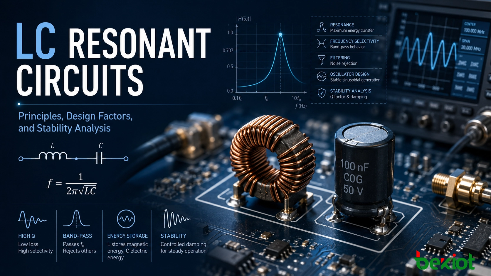
The most common formula used in LC circuit design is the resonant frequency equation. It shows that the resonant frequency depends on both inductance and capacitance. If either inductance or capacitance increases, the resonant frequency decreases.
f0 = 1 / (2π√LC)
This equation is an important design starting point, but it should not be treated as the final answer. In real circuits, winding resistance, equivalent series resistance, parasitic capacitance, trace inductance, and load interaction can shift the measured resonant point away from the ideal calculated value.
Why resonance is useful
Resonance is useful because it gives a circuit frequency selectivity. Instead of responding equally to all frequencies, an LC network can emphasize or suppress a specific band. This makes it valuable in communication systems, measurement circuits, RF front ends, signal filters, and oscillator designs.
In a receiver, resonance can help select one channel from many signals. In an oscillator, it helps define the output frequency. In a filter, it shapes the passband or stopband. In an impedance-matching network, it helps improve power transfer at a chosen operating frequency.
Series and Parallel LC Circuits
Series resonance
In a series LC resonant circuit, the inductor and capacitor are placed in the same current path. Away from resonance, the circuit presents reactance and restricts current flow. At resonance, the inductive and capacitive reactances cancel each other, so the total impedance drops to its lowest value.
Because impedance becomes low at the resonant point, current reaches its maximum value for a given source voltage. This makes series resonance useful in band-pass structures, tuning stages, and circuits that need to accept a selected frequency efficiently.
A practical point should not be ignored: even if the supply voltage is moderate, the voltage across the individual inductor and capacitor can become high near resonance. Designers should check voltage ratings, current stress, heating, and safety margins before finalizing the circuit.
Parallel resonance
In a parallel LC resonant circuit, the inductor and capacitor are connected in parallel. At resonance, large currents may circulate between the two branches, but from the viewpoint of the source, the input impedance becomes high.
This behavior makes parallel resonance useful where a selected frequency needs to be blocked, sustained, or presented as a high-impedance tuned load. It is common in oscillator tanks, tuned RF loads, selective filtering stages, and frequency-control networks.
Parallel resonance is especially important in oscillator design because the network can store energy efficiently while providing a resonant load to the active device. Even so, real performance is still shaped by component losses and by the loading effect of the surrounding circuit.
Series and parallel LC circuits behave differently, so testing should consider topology, loading, and measurement setup.
Key Parameters That Shape Performance
Choosing inductance and capacitance
The first design step is to define the target resonant frequency and select practical L and C values. Many different combinations can produce the same theoretical resonance, but not all of them are suitable for real hardware.
Designers must consider component size, availability, tolerance, current rating, voltage rating, temperature behavior, parasitic loss, and cost. At lower frequencies, larger inductors or capacitors may be needed, which can increase size and losses. At higher frequencies, smaller component values are common, but PCB parasitics become more influential.
A good design process usually compares several L and C combinations instead of accepting the first calculated pair. The best choice is the one that balances resonance accuracy, stability, manufacturability, and long-term reliability.
Q factor and bandwidth
Q factor is one of the most important measures of LC resonant circuit performance. It describes how efficiently the circuit stores energy compared with how much energy it loses during each cycle. A high-Q circuit has sharper selectivity and a narrower bandwidth. A low-Q circuit has heavier damping and a broader response.
The relationship between Q and bandwidth is important in practical design. A narrowband receiver or filter may need a high Q to separate nearby frequencies. However, a high-Q circuit can also become more sensitive to component tolerance, temperature drift, and loading.
Q is not determined by the schematic alone. It also depends on inductor quality, capacitor loss, PCB layout, source impedance, load impedance, and coupling to nearby circuits. This is why measured Q can differ from the theoretical value.
Resistance and damping
No physical LC circuit is completely lossless. Inductors include copper resistance and sometimes core loss. Capacitors include equivalent series resistance and dielectric loss. These resistive effects convert part of the stored energy into heat and reduce the sharpness of resonance.
Damping determines how quickly oscillation decays. In a passive resonant network, damping broadens the response and lowers the resonant peak. In an oscillator, the active device must provide enough gain to compensate for these losses and sustain oscillation.
For this reason, many real LC circuits are better understood as RLC networks. Including resistance in the analysis gives a much more realistic view of how the circuit will behave in actual hardware.
A Practical Design Process
Define the design purpose
A good LC resonant circuit starts with a clear purpose. The circuit may be used for frequency selection, oscillation, filtering, impedance matching, sensing, or noise suppression. Each application has different requirements for center frequency, bandwidth, insertion loss, stability, voltage handling, and tuning range.
For example, an RF front-end tuning circuit and a laboratory oscillator may operate near the same frequency, but their priorities can be very different. One may focus on selectivity and compact layout, while the other may require stable adjustment, low drift, and easy measurement access.
Calculate the first component values
After the target frequency is known, the designer can choose either L or C as the starting value and calculate the complementary component. At this stage, standard component values, tolerance classes, package types, and current or voltage ratings should already be considered.
It is usually better to compare several nearby combinations. A slightly different inductor and capacitor pair may offer better Q, lower loss, easier sourcing, or better stability during mass production.
Account for parasitics early
After the initial calculation, the next step is to consider non-ideal effects. PCB trace length, pad geometry, component leads, connectors, shielding, and nearby ground structures can all change the effective inductance or capacitance seen by the circuit.
At high frequencies, parasitic effects can shift the resonant frequency significantly or create unintended resonance points. This is why a circuit that looks correct in a simplified calculation may behave differently on a real PCB.
Equivalent series resistance, stray capacitance, leakage paths, and realistic source and load impedances should be included as early as possible in simulation and design review.
Simulate, prototype, and measure
Simulation helps predict resonant frequency, bandwidth, impedance behavior, peak response, and tolerance sensitivity before hardware is built. SPICE-based tools are useful for comparing component choices and understanding how losses and loads affect the response.
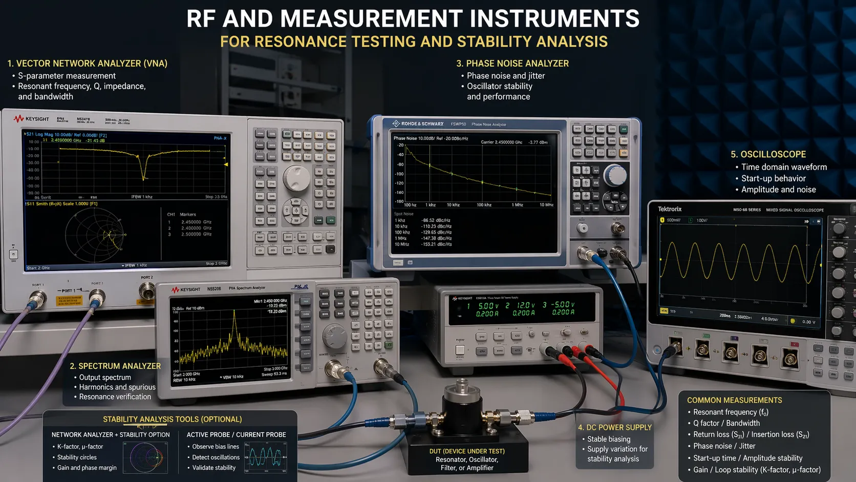
However, simulation cannot replace bench testing. Real components, assembly variation, fixture effects, probe loading, and PCB layout details can all change the final result. Prototype measurement remains essential, especially in RF and frequency-critical designs.
Adjustable capacitors, trimmers, layout revisions, and controlled tuning points are often used to align the final circuit after measurement.
A calculated resonant frequency is only the beginning. A stable LC design comes from calculation, simulation, layout control, and measurement working together.
Common Applications
RF tuning and signal selection
One of the most common uses of LC resonance is RF tuning. A resonant circuit can favor one frequency band while attenuating signals outside that range. This is essential in radio receivers, tuners, front-end filters, and communication circuits.
Because RF tuning often requires narrow frequency control, high-Q components, careful shielding, and compact layout are important. Small parasitic changes can become significant as the operating frequency rises.
Oscillators and frequency generation
LC tank circuits are widely used in sinusoidal oscillators, including Colpitts and Hartley oscillator designs. In these circuits, the LC network sets the oscillation frequency, while the active device restores the energy lost in each cycle.
Oscillator circuits require careful attention to stability. Temperature drift, power supply variation, component tolerance, and parasitic coupling can all affect output frequency. For this reason, oscillator-grade LC networks often require better components and tighter layout control than simple demonstration circuits.
Filters and impedance matching
LC elements are also important in analog filters and impedance-matching networks. In filters, they help create passbands and stopbands that are much sharper than simple resistive circuits. In matching networks, they transform impedance to improve energy transfer at a target frequency.
These functions are especially useful in RF transmitters, receivers, antenna interfaces, and wireless power or signal-transfer systems. However, matching and filtering are frequency-dependent, so the design must be optimized for the actual operating band.
LC circuit applications depend on accurate testing, controlled layout, suitable components, and stable operating conditions.
Stability Issues in Real LC Circuits
Component tolerance
Real inductors and capacitors are not exact. Their measured values can differ from the nominal values printed in the datasheet. Since the resonant frequency depends directly on both L and C, component tolerance can shift the final operating point.
In broad-response circuits, this shift may be acceptable. In narrowband filters, RF tuning stages, or precision oscillators, even a small value error can matter. Tighter-tolerance components or calibration adjustments may be needed.
Temperature and environmental drift
Temperature changes can affect both inductance and capacitance. Some capacitor dielectrics are more stable than others, and some magnetic core materials change behavior with temperature. These changes can move the resonant frequency away from its intended value.
Humidity, vibration, mechanical stress, enclosure structure, and nearby materials can also influence performance. In practical designs, stability depends not only on the schematic, but also on the physical environment and packaging method.
Loading and coupling
An LC circuit rarely operates alone. It is normally connected to a source, amplifier, antenna, measurement instrument, or another circuit stage. These connections load the resonant network and can change its Q, bandwidth, peak response, and sometimes its apparent resonant frequency.
Loading is also a measurement issue. A probe, cable, or instrument input may unintentionally alter the circuit being tested. Good measurement practice is therefore part of good LC circuit design.
PCB layout and parasitic elements
Parasitic capacitance, unwanted inductance, trace resistance, and unintended coupling are common reasons why practical LC circuits differ from ideal calculations. At low frequencies, these effects may be small. At higher frequencies, they can become a major part of the circuit behavior.
Short return paths, compact component placement, sensible grounding, controlled trace geometry, and appropriate shielding all help preserve the intended resonance. In many RF circuits, physical layout is almost as important as the schematic.
Design Practices for Better Stability
Stable LC resonant circuits are built through disciplined design. High-Q inductors, low-loss capacitors, suitable tolerance classes, compact layout, and thoughtful shielding can all improve frequency accuracy and response consistency.
Designers should also minimize unnecessary loading, evaluate temperature behavior early, consider component derating, and verify results through both simulation and measurement. In demanding applications, tuning provisions and calibration steps can make the difference between a theoretical design and a reliable final product.
The best LC resonant circuits are not only tuned to the correct frequency. They are engineered to stay stable under real operating conditions.
Conclusion
LC resonant circuits remain essential because they provide an efficient way to control frequency behavior in electronic systems. Their core principle is based on energy exchange between an inductor and a capacitor, but successful design requires more than applying the resonance formula.
Series and parallel topology, Q factor, resistance, damping, bandwidth, tolerance, thermal drift, loading, and parasitic effects all influence real performance. Whether the goal is RF tuning, oscillation, filtering, impedance matching, or signal conditioning, engineers must combine theory with practical measurement and stability analysis.
A strong LC resonant circuit is not only mathematically correct. It is stable in hardware, predictable in operation, and suitable for the demands of its real application.
FAQ
What is the main purpose of an LC resonant circuit?
The main purpose is to create a frequency-selective response. LC resonant circuits can pass, reject, generate, or shape signals around a selected frequency.
What is the difference between series and parallel resonance?
In series resonance, impedance becomes low and current reaches a maximum at the resonant frequency. In parallel resonance, input impedance becomes high, making it useful for tuned loads, tank circuits, and selective frequency networks.
Why is Q factor important?
Q factor shows how efficiently the circuit stores energy compared with how much it loses. A higher Q creates sharper selectivity and narrower bandwidth, while a lower Q creates broader response and heavier damping.
Why does the measured resonant frequency differ from the calculated value?
Differences usually come from component tolerance, parasitic capacitance, trace inductance, equivalent series resistance, loading, temperature drift, and measurement setup effects.
Are LC resonant circuits still used in modern electronics?
Yes. They are still widely used in RF systems, oscillators, analog filters, impedance-matching networks, sensing circuits, and many signal-processing applications.