How Should a VoIP Gateway Architecture Be Designed?
VoIP Gateway network architecture explained for PBX, SIP trunk, analog line and multi-site voice projects, covering signaling, RTP media, routing, security, QoS, redundancy and maintenance planning.
Becke Telcom
A VoIP Gateway is often described as a device for converting voice interfaces, but this explanation is too simple for real projects. In an actual communication system, the gateway may connect analog phones, FXO lines, FXS extensions, E1/T1 trunks, legacy PBX systems, SIP platforms, carrier trunks, emergency phones, fax machines, intercom devices, radio interfaces and IP networks. Once these systems are connected, the gateway becomes part of the whole voice architecture, not just a hardware converter.
Many gateway problems do not come from the device itself. Registration failure, one-way audio, wrong caller ID, unstable outbound calls, echo, failed fax transmission, NAT issues, security exposure and difficult troubleshooting are often caused by poor network architecture. A reliable design must define where the gateway is placed, how SIP signaling travels, how RTP media flows, how numbers are routed, how security is controlled and how the system will be maintained after deployment.
This article focuses on the practical design logic of VoIP Gateway network architecture. It is written for PBX migration, SIP trunk deployment, analog line integration, multi-site voice networking, enterprise telephony upgrades and industrial communication projects where old and new voice systems need to work together.
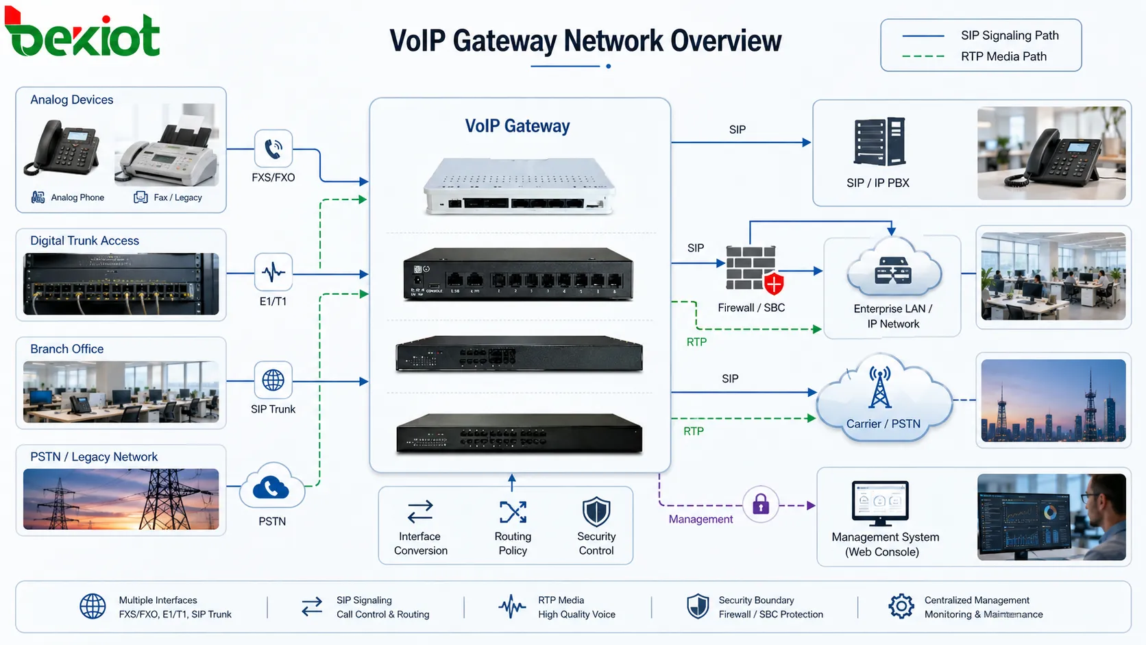
A good VoIP Gateway architecture should define interface access, SIP signaling, RTP media path, routing policy, security boundary and management access before deployment.
Start with the gateway role
Before drawing the network topology, engineers should first confirm what the gateway is expected to do. Some gateways mainly provide FXS ports for analog extensions. Some connect FXO lines to an IP PBX. Some convert E1/T1 or PRI circuits into SIP trunks. Some are used during PBX migration, allowing a legacy telephone system and a new SIP platform to coexist. The same product category may serve very different project goals.
If the role is unclear, the architecture can easily become confusing. A gateway used for analog extension access should not be designed in the same way as a gateway used for carrier trunk interconnection. A site gateway serving emergency phones should not be treated as a normal office voice device. The gateway role determines routing rules, security policy, redundancy requirements and maintenance priority.
Interface conversion is only the beginning
The basic function of a VoIP Gateway is interface conversion. It may convert analog FXS or FXO lines into SIP, connect digital trunks to an IP PBX, bridge old PBX resources with a modern communication platform or provide analog access for elevator phones, fax devices, door intercoms and emergency endpoints.
However, a gateway also participates in many deeper voice processes. It may handle SIP registration, trunk authentication, codec negotiation, number transformation, DTMF transmission, call progress tone detection, echo cancellation, fax relay, failover routing, CDR output, alarm reporting and remote management. These functions influence the stability of the entire voice network.
This is why VoIP Gateway design should not stop at “which ports are needed.” The project must also answer how calls enter the gateway, where they go next, which network path carries media, which users are allowed to call out and how failures will be detected.
The gateway is a network boundary
A VoIP Gateway often sits between two different communication worlds. It may connect analog and IP systems, PSTN and enterprise networks, a legacy PBX and a SIP server, a local site and a carrier trunk, or a private voice network and a public SIP service. Because it is a boundary point, it should be designed with clear protection and routing rules.
Without boundary planning, voice traffic may pass through the wrong path, unauthorized SIP attempts may reach the gateway, NAT may break media transmission, or outbound routes may bypass intended call policies. The architecture should define which systems can access the gateway, which ports are open, which networks are trusted and which traffic must be blocked.
Separate signaling and media
One of the most important ideas in VoIP Gateway architecture is that SIP signaling and RTP media are not the same thing. SIP signaling controls call setup, ringing, session negotiation, transfer and hang-up. RTP carries the actual voice packets that users hear.
In some networks, SIP signaling may pass through a PBX, SBC or SIP server, while RTP media may flow directly between the gateway and another endpoint. In other designs, both signaling and media are anchored through a central platform. Each approach has advantages, but the path must be intentional.
One-way audio is a typical result of ignoring this separation. A call may connect successfully because SIP signaling works, but audio may fail because RTP ports are blocked by a firewall, private IP addresses are advertised in SDP, NAT translation is incorrect or the media route does not match the signaling route. A gateway architecture must therefore design both paths from the beginning.
Core layers of the architecture
Access layer
The access layer is where physical voice resources enter the gateway. It may include analog phones, fax machines, elevator phones, emergency phones, door intercoms, FXO PSTN lines, E1/T1 circuits, radio interfaces or legacy PBX trunks. This layer determines the port type, cable requirements and electrical conditions of the project.
For analog access, engineers should check cable distance, ringing load, impedance, grounding, surge protection, line voltage, fax needs and endpoint compatibility. For digital trunks, they should confirm clock source, framing, signaling mode, channel mapping and number format. These details are easy to miss when the project team focuses only on SIP settings.
Voice service layer
The voice service layer includes the IP PBX, SIP server, unified communication platform, call center platform, dispatch system or carrier SIP trunk. The gateway must communicate with this layer using the correct registration method, authentication mode, dial plan, codec policy and signaling behavior.
Some gateways register to the PBX as SIP accounts. Some work as peer trunks without registration. Some connect to multiple PBX systems or carrier platforms. The architecture should choose a working mode based on the project, instead of keeping default settings and hoping the network will adapt.
Transport network layer
The transport layer carries SIP and RTP traffic across switches, routers, VLANs, WAN links, firewalls, VPNs, SD-WAN services, private lines or internet paths. Voice quality depends heavily on this layer. A gateway cannot create stable audio if the network path is congested, unstable or poorly segmented.
A proper transport design should consider latency, jitter, packet loss, routing predictability, bandwidth, QoS marking, firewall behavior and NAT traversal. The network must be planned for peak call volume, not only for a single successful test call.
Management layer
The management layer includes configuration access, logs, alarms, SNMP, syslog, call detail records, packet capture, firmware management, backup files, monitoring dashboards and remote maintenance permissions. This layer is often ignored during installation, but it becomes critical when calls start failing.
Good architecture separates management access from untrusted voice access where possible. Administrators should be able to monitor trunk status, port alarms, registration state, CPU load, packet loss, call failures and line faults without exposing the gateway to unnecessary risk.
Choose the right SIP mode
SIP registration mode is common when the gateway behaves like a group of SIP extensions. For example, an FXS gateway may register multiple analog ports to an IP PBX, allowing analog phones to work as internal extensions. This design is easy to manage when each analog port maps to a clear extension number.
Peer trunk mode is more common in PBX-to-PBX, PBX-to-carrier or digital trunk-to-SIP scenarios. Instead of registering many accounts, the systems trust defined IP addresses and route calls by trunk rules. This mode can be efficient, but it requires strict IP access control, firewall rules and route permissions.
The decision should be made early. Mixing registration mode and peer trunk mode without documentation can create confusing routes, duplicate caller IDs, unexpected authentication failures and difficult troubleshooting.
Plan the number route carefully
A VoIP Gateway often connects systems that use different dialing habits. Analog phones may dial short internal extensions. A carrier may require national or international number formats. A legacy PBX may send access codes, leading zeros or internal prefixes. A SIP platform may expect DID, DOD or extension-based routing.
Number transformation should therefore be written as part of the architecture. Engineers should define inbound rules, outbound rules, emergency numbers, extension ranges, trunk prefixes, caller ID format, DID handling, DOD handling, failover routes and blocked destinations.
Poor number planning can make a technically healthy system look broken. Calls may reach the gateway and still fail because the far side receives the wrong format. In larger deployments, unclear dial plans also increase the risk of toll fraud, route loops and inconsistent user experience across sites.
Design the RTP media path
RTP path planning decides where voice packets travel after a call is established. Direct media between gateway and endpoint may reduce delay and reduce load on the PBX. Media anchoring through a PBX or SBC may improve NAT handling, recording, policy control and topology hiding.
There is no single best answer for every project. A local office gateway may use direct media for internal calls. A SIP trunk connected to a public carrier may require media anchoring through an SBC. A call center may need all media to pass through a recording platform. The architecture should match the service requirement.
RTP planning should include IP addressing, NAT behavior, firewall pinholes, RTP port ranges, codec policy, QoS marking, packetization interval, recording requirements and failover path. If a call connects but has no voice, the media path should be checked before changing random SIP settings.
Codec policy affects quality and bandwidth
Codec selection affects voice quality, bandwidth usage, delay, compatibility and processing load. Internal calls may use higher-quality codecs when bandwidth is sufficient. PSTN or carrier interconnection may require narrowband codecs. Low-bandwidth WAN links may need compression, but compression can increase delay and reduce audio quality.
A good architecture avoids unnecessary transcoding. Each transcoding step consumes gateway or server resources and may degrade audio. Where possible, the gateway, PBX, carrier and endpoint should share a common codec for the main call paths.
Codec policy should be tested with real routes. A codec that works between two IP phones may not work correctly through a carrier trunk, fax device, analog adapter or recording platform. Compatibility testing is part of architecture validation.
DTMF and fax need special attention
DTMF is used for IVR menus, voicemail access, conference PINs, door opening, remote commands and call control. A gateway may transmit DTMF in-band, through RTP events or through SIP signaling. The correct method depends on the PBX, carrier, codec and application.
DTMF problems are common in gateway projects. Users may report that IVR menus do not recognize key presses, door opening commands fail or remote systems receive duplicate digits. The DTMF method should be standardized across gateway, PBX, trunks and endpoints, then tested with real services.
Fax is another sensitive service. A VoIP Gateway may support T.38 fax relay or fax passthrough. The correct choice depends on carrier support, endpoint behavior, codec policy and network stability. If fax matters to the project, it should be treated as a separate test case instead of being assumed as a normal voice call.
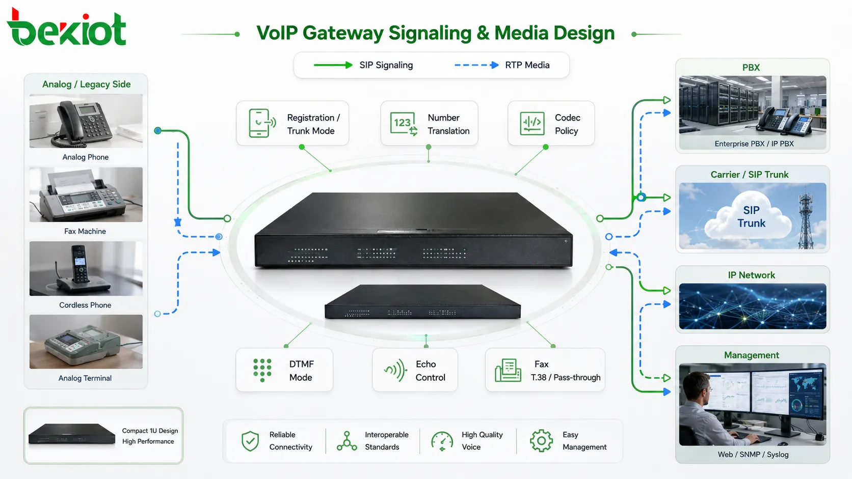
SIP mode, number translation, RTP routing, codec selection, DTMF handling and fax support should be designed together rather than configured separately.
Security starts from exposure control
A VoIP Gateway should not be exposed to every network segment by default. SIP ports, RTP ports, web management, SSH, SNMP and provisioning interfaces should be protected by firewall rules and access control lists. Only trusted PBX systems, SBCs, management servers and carrier addresses should reach the gateway where possible.
Direct exposure can lead to SIP scanning, unauthorized calls, toll fraud, configuration attacks or service disruption. Changing the default password is necessary, but it is not enough. Security should be designed at the network layer, routing layer and device layer.
When a gateway must communicate through public networks, using an SBC, VPN or controlled private connection is usually safer than placing the gateway directly on the internet. If direct access is unavoidable, IP restrictions, strong authentication, call barring, destination limits, logging and active monitoring become essential.
NAT traversal should not be guessed
NAT problems are a major cause of gateway call failures. SIP messages may carry private IP addresses in SDP, while RTP packets need separate port mappings. A firewall may allow signaling but block media. A router may close UDP sessions too quickly. These problems often appear as one-way audio, no audio or calls that fail after a short time.
The architecture should define whether the gateway uses a public IP address, private IP address, SBC, VPN, static port forwarding or keepalive mechanism. SIP headers, SDP addresses, RTP port ranges and firewall timeout values should be verified during testing.
QoS must cover the whole path
Voice packets are sensitive to delay, jitter and packet loss. QoS marking helps switches and routers prioritize SIP and RTP traffic over less time-sensitive data. RTP media usually needs higher priority because users hear media problems immediately.
QoS only works when the whole path respects it. Marking packets at the gateway is not useful if switches, firewalls, WAN links or carriers ignore the marking. Engineers should verify QoS behavior from gateway to PBX, from PBX to carrier and across branch links if multi-site calling is involved.
Bandwidth planning should include simultaneous call volume, codec overhead, RTP headers, VPN encapsulation, failover scenarios and future expansion. Voice problems often appear during busy periods, not during initial testing with one or two calls.
Reliability is part of the architecture
If the gateway supports important services, one device or one trunk may not be enough. Failure can affect analog extensions, PSTN access, emergency phones, elevator phones, fax service, dispatch communication or carrier connectivity. Redundancy should be considered according to service importance.
Redundancy may include backup gateways, secondary SIP trunks, local PSTN lines, distributed site gateways, dual network paths, UPS power, backup configuration files and automatic failover routes. The design should define what happens when the primary gateway, PBX, WAN link, carrier trunk or power source fails.
Failover should be tested. A route that exists on paper may not work under real outage conditions. Emergency numbers, service hotlines, alarm phones and critical analog endpoints should have priority in continuity testing.
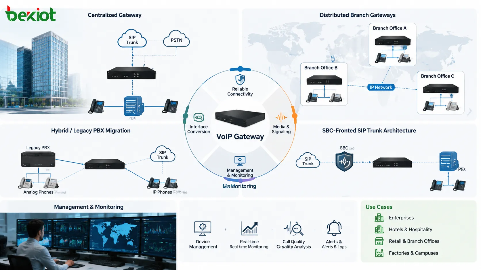
Centralized or distributed deployment
A centralized gateway architecture places the main gateway or gateway cluster at a central site. Branches send calls through the central voice system. This simplifies trunk management, policy control and monitoring, but it depends heavily on WAN reliability.
A distributed gateway architecture places gateways at different branches, buildings or operating sites. Each site can connect local analog endpoints, local trunks or emergency lines. This improves local survivability, but it requires consistent management of numbering, firmware, route rules, security policy and configuration backup.
Many organizations use a hybrid model during migration. Legacy PBX systems, analog devices, SIP trunks and new IP endpoints coexist for a period of time. In this case, gateways bridge old and new systems while the project gradually moves toward the target architecture.
When an SBC should be added
An SBC is often useful when the VoIP Gateway connects to public SIP trunks or untrusted external networks. The SBC can provide topology hiding, SIP normalization, NAT traversal, media anchoring, security filtering and carrier interconnection control.
In an SBC-fronted design, the gateway focuses on local interface conversion and internal voice access, while the SBC manages the external SIP boundary. This can reduce direct exposure of the gateway and make carrier interconnection easier to control.
However, an SBC also adds another system to manage. The architecture should define responsibilities clearly: which system handles routing, which system anchors media, which system provides security filtering and which system stores call records.
Gateway deployment may be centralized, distributed, hybrid or SBC-fronted depending on scale, survivability, security and migration requirements.
Management and monitoring cannot be optional
A gateway may work quietly for months, but when problems appear, administrators need visibility. Monitoring should include registration state, trunk status, analog port status, E1/T1 alarms, call failure rate, CPU load, memory usage, packet loss, jitter, network reachability and power condition.
Logs and packet capture are also important. SIP traces, RTP statistics, CDR records, DTMF events, port events and error logs help engineers determine whether a problem is caused by routing, signaling, codec negotiation, media path, analog line behavior or network transport.
Remote maintenance should be controlled. Administrators need secure access to diagnostic data, but management interfaces should not be exposed unnecessarily. For remote sites, syslog, SNMP, VPN access and controlled packet capture can reduce troubleshooting time.
Documentation keeps the system maintainable
A VoIP Gateway can contain many settings that are easy to forget: port mapping, extension mapping, inbound routes, outbound routes, number transformation, codec priority, DTMF mode, fax mode, trunk authentication, IP access lists, firewall rules and failover logic.
If these settings are not documented, future troubleshooting becomes slow and risky. Documentation should include topology diagrams, IP addresses, VLANs, SIP peers, RTP port ranges, dial plans, emergency routes, backup trunks, firmware versions, configuration backup locations and routine test procedures.
Change records are equally important. A small change to a dial plan or codec setting may affect many users. Good maintenance practice records what was changed, when it was changed and why it was changed.
Common design mistakes
Mistake
Typical Result
Better Design Approach
Only checking SIP registration
Calls connect but there is no audio or one-way audio
Design SIP signaling and RTP media paths together
Using default dial plans
Wrong routing, failed outbound calls or poor caller ID behavior
Document number rules for inbound, outbound, emergency and failover calls
Exposing the gateway directly
SIP scanning, toll fraud and unauthorized access
Use firewall rules, ACLs, SBC, VPN and strong authentication
Ignoring analog line conditions
Echo, ringing failure, unstable fax or device compatibility issues
Check REN load, grounding, impedance, surge protection and cable distance
No delivery documentation
Slow troubleshooting and high maintenance risk
Deliver topology, dial plan, configuration backup and test records
Evaluation standards after deployment
Call routing accuracy
The first evaluation standard is whether calls follow the intended route. Internal calls, outbound calls, inbound calls, DID calls, DOD calls, analog endpoint calls, emergency calls, trunk calls and failover calls should all be tested. A single successful call does not prove the architecture is complete.
Voice quality stability
Voice should remain clear under normal and busy conditions. Engineers should check delay, jitter, packet loss, echo, codec behavior, DTMF recognition, fax performance, recording quality and call release behavior. Busy-hour testing is more useful than testing only in an empty network.
Security control
The gateway should only allow intended access and intended calls. SIP peers, management interfaces, outbound routes, destination permissions, passwords, firewall rules and log records should be reviewed. Security should be verified, not assumed.
Service continuity
The architecture should define what happens during gateway failure, PBX outage, WAN loss, power interruption or carrier trunk failure. Critical services should have backup paths or clear recovery procedures.
Operational maintainability
A good gateway architecture is not only stable on the day of installation. It should remain manageable after months or years of operation. Monitoring, logs, backup files, documentation, firmware control and routine test procedures determine long-term reliability.
Final view
VoIP Gateway network architecture should be designed around the complete voice path, not only around the gateway hardware. The design must cover access interfaces, SIP signaling, RTP media, number routing, codec policy, DTMF, fax, echo control, NAT traversal, security, QoS, redundancy, monitoring and maintenance.
The gateway may connect analog endpoints, PSTN lines, digital trunks, SIP servers, carrier trunks, legacy PBX systems, emergency phones, fax devices, radio interfaces and multi-site networks. Its architecture should make these resources communicate in a controlled, secure and predictable way.
The strongest design uses clear boundary planning, documented dial plans, predictable media routes, protected access, QoS-enabled transport, tested failover and visible monitoring. When these elements are handled properly, the VoIP Gateway becomes a stable bridge between legacy telephony and modern IP communication systems.
FAQ
Why does a VoIP Gateway need network architecture planning?
Because the gateway is connected to signaling, media, routing, security, analog lines, trunks and management systems. Without architecture planning, calls may connect incorrectly, audio may fail, routes may become unsafe and troubleshooting may become difficult.
What is the most common cause of one-way audio?
One-way audio usually happens when SIP signaling succeeds but RTP media is blocked, translated incorrectly or routed through the wrong path. Firewall rules, NAT settings, SDP addresses and RTP port ranges should be checked.
Should every VoIP Gateway use SIP registration?
No. SIP registration is suitable for many extension-style deployments, especially FXS gateways. Peer trunk mode may be better for PBX interconnection, carrier trunking or digital trunk conversion. The choice depends on the project architecture.
When should an SBC be used with a VoIP Gateway?
An SBC is useful when the gateway connects to public SIP trunks, untrusted networks or complex NAT environments. It can improve security, topology hiding, SIP normalization, media anchoring and carrier interconnection control.
How can gateway reliability be improved?
Reliability can be improved through backup gateways, secondary trunks, UPS power, clear failover routes, QoS, controlled security policy, configuration backups, monitoring, surge protection and routine call-path testing.